I did a Reprint; because, I didn’t Deselect “Fit Picture To Frame” Option.
The circle came out as a 5-3/4" Diamter Circle.
I did a Reprint; because, I didn’t Deselect “Fit Picture To Frame” Option.
The circle came out as a 5-3/4" Diamter Circle.
I found the Measurement Data on my own.
Awe Man…
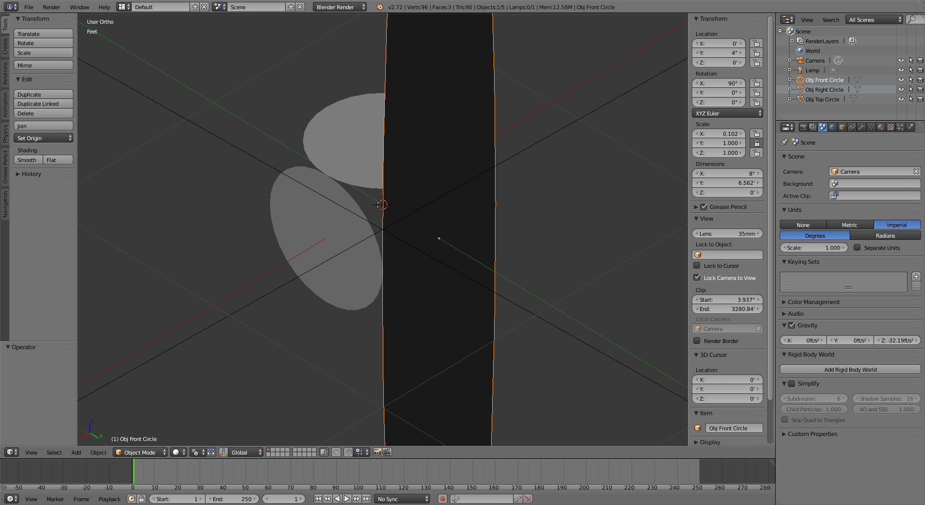
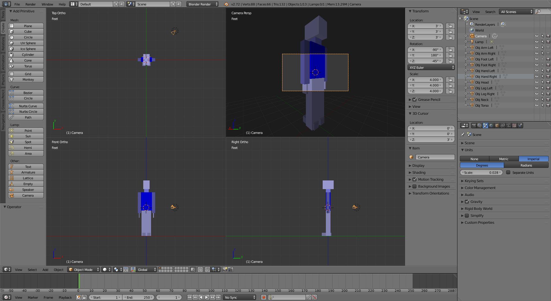
LOCATION: X=0’,Y=0’,Z=13.12336’
ROTATION: X=0*,Y=-0*,Z=0*
[XYZ Euler]
SCALE: X=4.000,Y=4.000,Z=1.000
DIMENSIONS: X=26.247’,Y=26.247’,Z=0’
Definitely NOT what I was wanting for Drawing Dimensions.
don’t forget to Cltr-A your objects!
scale should be one!
happy bl
ooo…I can specify Dimension Inches by typing “in” in the XYZ Boxes.
awe man…the decimal only goes to 3 places.
1/8" = 0.125
1/16" = 0.0625
1/32" = 0.03125
1/64" = 0.015625
Blender 1/16" = 0.063
DeltaCAD 1/32" = 0.0313
Very Disappointing…and Very Bad for my Graphic Drawing needs.
= = = = = = = = = = = = = = = = = = = = = = = = = = = =
?What do the SCALE Values represent anyway?
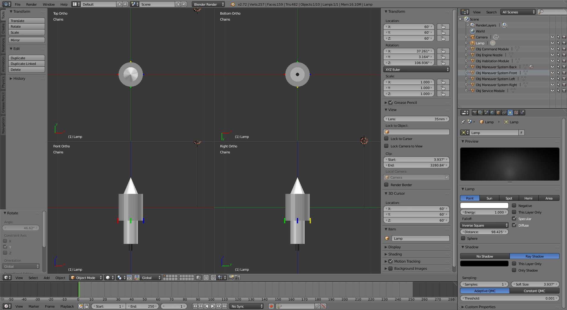
The Imperial Feet Measurements are more suited for my FLOWER CHILD PROJECT Manned Spacecraft Design Concept than for what I want to do with the “IsisHead” Project.
I need to work on the Engine Nozzle shape; but, its presence is more important at this point.
The Command Module is a 13’0" Diameter by 15’0" Long Conical Structure.
The Habitation Module is a 22’0" Diameter by 24’0" Long Cylender.
The Service Module is 13’0" Diameter by 24’0" Long Cylender.
The Engine Nozzle is supposed to be a 6’0" Long by 6’0" Diameter (at one end) and 3’0" Diameter (at the other end) Cylender Structure.
The Maneuver Systems are supposed to be the Apollo CSM Reaction Control Systems; which, I assume are 1’0"x1’0"x5’0" Cube Structures (without the Nozzles).
= = = = = = = = = = = = = = = = = = = = = = = = = = = = = = = = = = = = = = = = = = =
The overall concept of my FLOWER CHILD PROJECT is to redesign the Apollo CSM/LM Spacecraft Design into an Orbit-To-Orbit Spacecraft Design.
The Apollo CSM/LM Spacecraft in its 1970s configuration isn’t suitable for Earth-Luna Orbit-To-Orbit Spaceflight.
Some of my concepts for revisioning the Apollo CSM/LM Spacecraft into an Orbit-To-Orbit Spacecraft include expanding the Fuel Capacity of the Service Module; and, replacing the Service Module Main Engine with a Modified F-1 Engine that burns Cryogenic Fuel.
This drawing doesn’t represent my Revision Concepts for my FLOWER CHILD PROJECT Spacecraft Designs.
The Habitation Module is 22 Feet in Diameter; while, the Command Module and Service Module are 13 Feet in Diameter. Although the Lunar Module Main Structure may have been closer to 13 Feet in Diameter, I decided to use the Lunar Module Landing Gear Dimensions as the Habitation Module Diameter.
The FLOWER CHILD PROJECT Spacecraft Design wasn’t originally conceived for landing Humans on Luna; but, having Humans remaining in Lunar Orbit for the duration of the Lunar Mission.
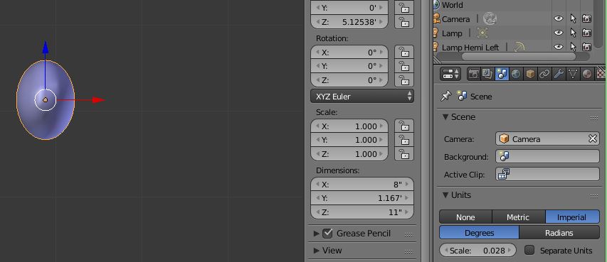
you can add like a cylinder and in N panel dimensions set the X Y Z value!
for the inch higher precision you might
with a scale of 1 blender is limited to numbers like 9999.999 Max 7 digits !
now if you want more precision below you can change the scale of the scene
X 10 that would add one digit on the right but remove one on the left!
999.9999 still limited to 7 digits!
X 100 gives 99.99999
you can enter in field ln = 12/32 but wont show it in 1/32 only in decimals
The Computer Photo Application that I am using is already Defaulted by the Computer; thus, I don’t know which Photo/Video Application is being used.
Different Text & Drawing Applications affect a specific Printer differently in terms of Page Formats; and, all Printers are different from each other in terms of Page Formats.
On the N Panel, ?what is Scale?
The Scene Panel Units Section allows me to create 1 Inch Grids; but, the Decimal System only goes 3 Places.
Would be nice if I could Sub-Divide the Inch Grids.
5ft10inHumanFemale#0.blend (1.13 MB)
wow…The Mega-Scale is great for World Map Generation…maybe even Star Map Generation…for Roleplaying Game World Settings.
I know how to change the Face Sizes of the Nozzle; but, just needed some time in figuring it out. At the time, I wasn’t interested in spending an additional 30 minutes to 1 hour trying to find the Control Systems to do the Nozzle properly.
Yea…I am still a Newbie with Blender.
Actually, that is how I do Create & Resize & Rotate & Move Objects within Blender.
I am not comfortable with the idea of using Shortkeys. FIRST: I am a bad typist. I miss my keys alot; and, hitting 2 Keys at the same time by accident is common for me. SECOND: I want to be familiar with the Control System Features before trying to figure out the Hotkey Settings.
Most commands are available as short -cut or in menus
so you can learn short cut as you go along!
when you scale in object mode it affects the object scale in N panel
so get use to always Ctrl-A select Rot and scale you object often!
the N panel dim gives you\ the real dimensions of you object of the scale is = 1
again if scale is not = 1 then Ctrl-A the ob
happy bl
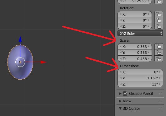
I think this is what I am trying to do with my “IsisHead” Project.
This Image should clarify things alot.
Oversimplification…But it also a Starting Point.
The N Panel Scale Numbers & Dimension Numbers are affected by the Units Scale Setting.
Thus changing the Unit Scale number changes both the N Panel Scal Number and the N Panel Dimension Number.
On the N Panel…The Scale Numbers and the Dimension Numbers are fixed to each other regardless of the Units Panel Scale Number. That is, with a given Units Panel Scale Number, a given N Panel Scale Number will result in a specific N Panel Dimension Number; and, a given N Panel Dimension Number will result in a specific N Panel Scale Number.
However, change the Units Panel Scale Number; then, the forementioned given N Panel Scale number will result in a new specific N Panel Dimension Number that is specific the new Units Panel Scale Number; and, the forementioned N Panel Dimension Number will result in a new specific N Panel Scale Number that is specific to the new Units Panel Scale Number.
?How am I supposed to know, or figure out, 1" in the Blender Application is supposed to equal to 1" on a Printer Printout?
With DeltaCAD 3.0, as long as I kept my Drawingings within 8"x10-1/2" Dimensions when using 8-1/2"x11" Letter Paper, then, my DeltaCAD Printouts do come out to 1" with the DeltaCAD Application = 1" on the Printer Printout.
= = = = = = = = = = = = = = = = = = = = = = = = = = = = = = = = = = = = = = = = = = =
?How did you put those Arrows into your Screenshot?
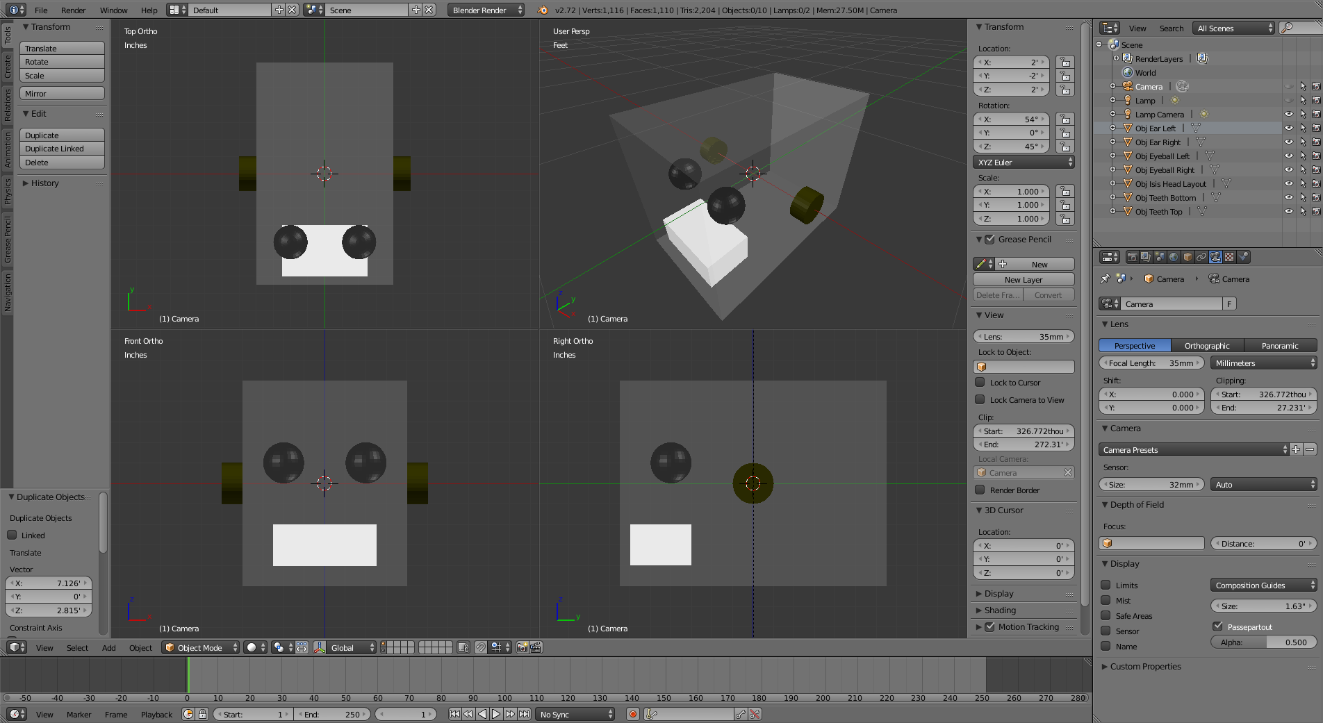
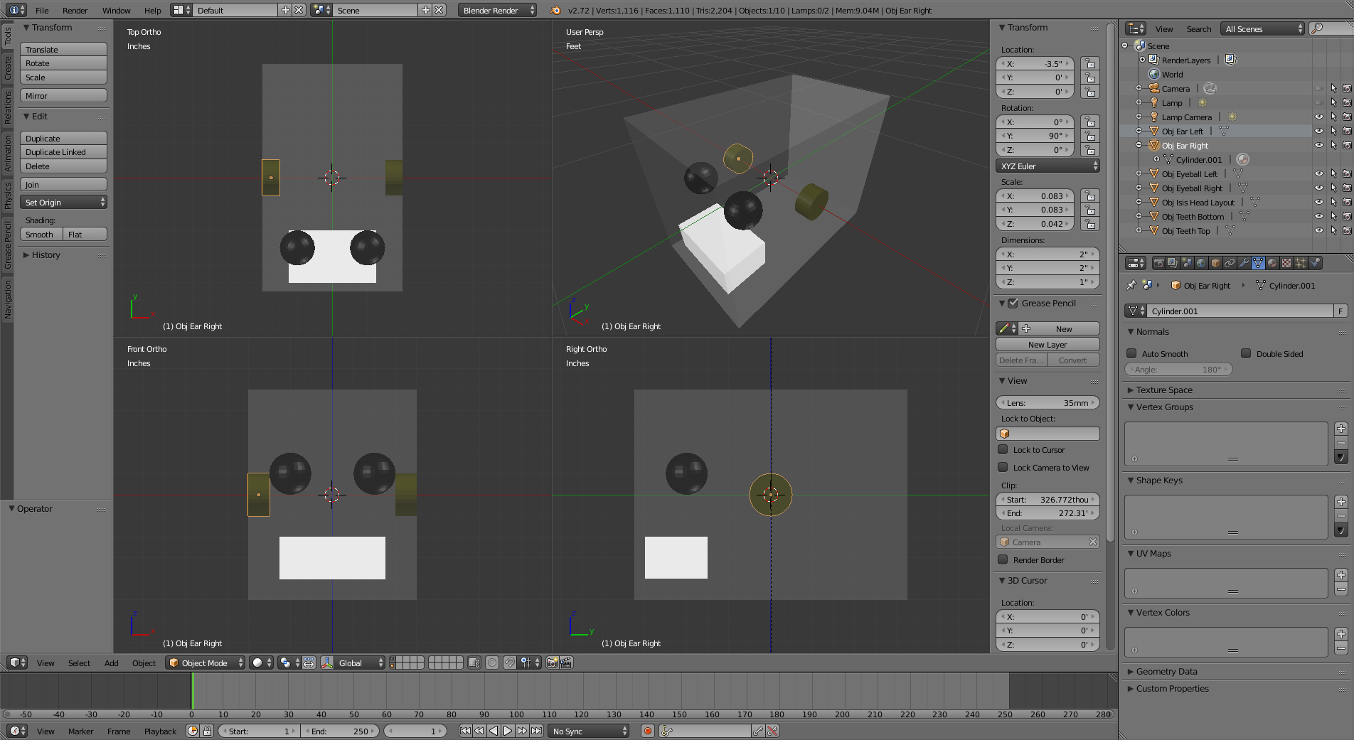
Oops…My earlier “IsisHead” Project is wrong. The Ears are supposed to be inside the Head Layout. Like this.
these are the basics of blender
you should take time to do a few basic tutorials then it would make sense.
and told you Blender is not a CAD soft !
things are totally different but don’t forget that blender can do a lot of animation rigging physics!
happy bl
Bwhaha,just give it up man ![]()
I suggest you check out a few things people have created in Blender to get an idea what the program can do and what it is for.
You mentioned in a previous post that you and your brother use blender completely differently,that may be part of the problem.We don’t know how experienced your brother is with blender but he probably has a better grasp of it if he has been using it longer then you,you may want to learn from him to see what he does differently and then ask questions once you have a basic grasp of Blender.
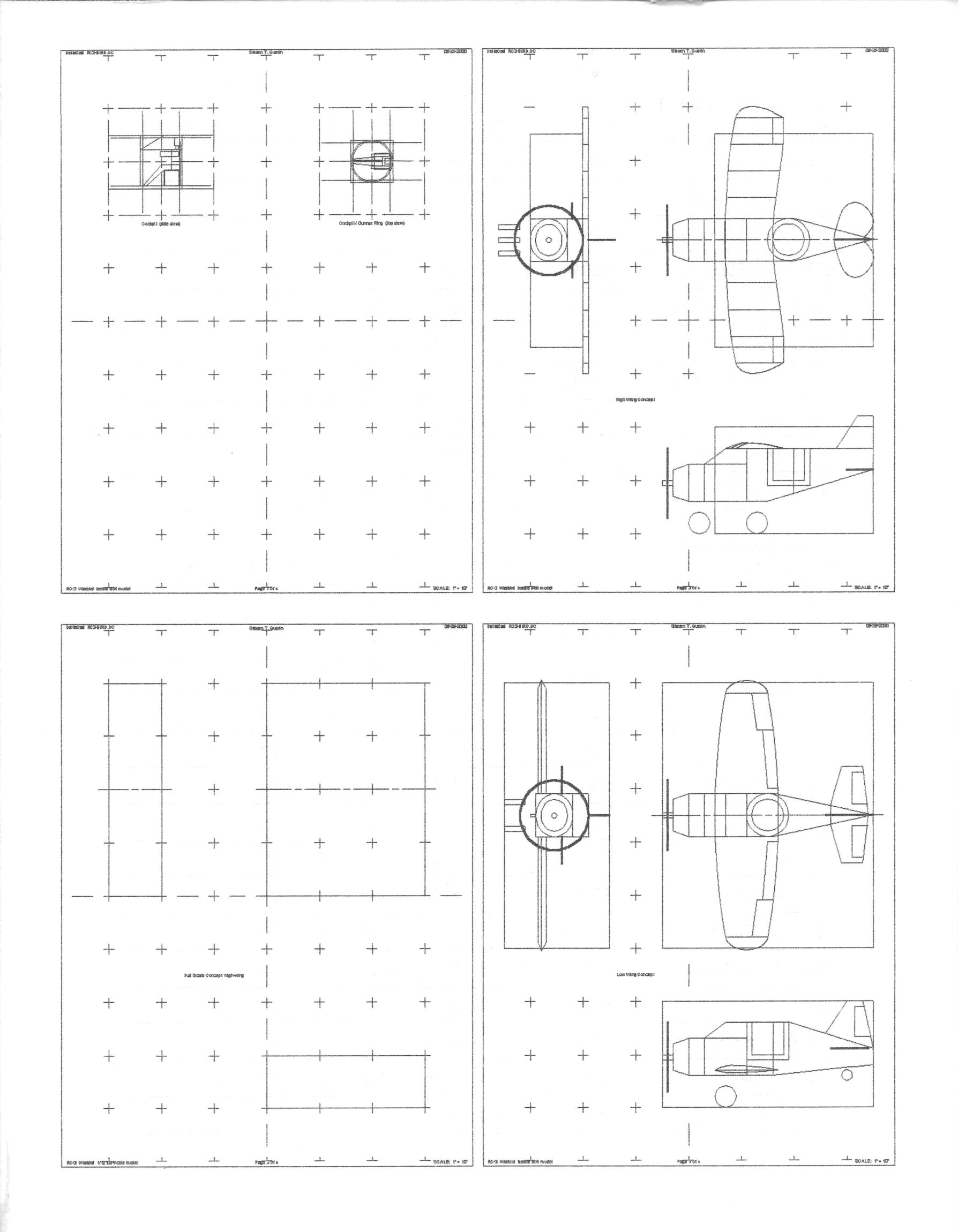
The above is a Single-Page Printout of a Multi-Page DeltaCAD 3.0 Drawing; even though, it was created as a Multi-Page Printout Drawing…4 Pages of 1"=1" Scale Drawing Printouts.
This is due to the quirks in the DeltaCAD Application and/or Computer Operating System and/or Printer System.
Because this DeltaCAD Drawing was created on a Computer-Printer Combo System that I had used many years ago; thus, I am no longer using that Computer-Printer Combo, I am unable to make a 4-Page 1"=1" Scale Drawing Printouts; without, having to do some major reworking on the DeltaCAD 3.0 Drawing itself.
It would be much simpler just to restart this project from scratch; which, would require trying to configure the DeltaCAD Drawing for 4-Page Printouts with my current Computer-Printer System.
I don’t remember if this DeltaCAD 3.0 Drawing is Layered or not. I think it is. The Printer was a Dot Matrix Black-Only thing; thus, even though, this project was done with Color-Coded Lines, that fact wouldn’t show up as a Multi-Layered Printout.
This was an R/C Airplane Concept for Barbie Dolls to ride in.
Yea…I do agree.
It will take alot of Experience to rig up something that will Printout in 1"=1" Scale.
I am too new at Blender to do that.
My brother has been using Blender for about a year creating Business Logos and “Photoshopping” Pictures & Videos.
Hi there…
I think what you need is “precision modelling”. It helps me a lot (It’s in the old version of Blender - it still helps)
http://wiki.blender.org/index.php/Doc:2.4/Books/Blender_Precision_Modelling_Guide
I did look at it; and, at the Core Website.
It is inspiring.