My FLOWER CHILD PROJECT was originally created on DeltaCAD 3.0. These are my Blender versions of my DeltaCAD 3.0 Drawings that are part of my “FLOWER CHLD PROJECT Presentation Folder”.
I had been working on the Android Drawing for awhile; so, I hadn’t gotten around to putting the Elbows and Knees in their places on the Android.
Glad you use blender for CAD. (You are planning to build space rockets? For that to work we’d need to make progress on our open source metal 3D printer I think. see buildtheenterprise.)
Precision modeling has its quirks while possible. A recent blendercode commit now allows to fully set a value to 0 (thanks for that). The main quirks are that at times you have some odd numbers like 2.9999999999 instead of 3. Just re-set the value to the even value then. It’s important to enter some values manually in blender if you want high precision. It’s also helpful to use snapping to the grid. This will fix heaps of issues for you.
Personally I’ve never seen a more promising program for CAD than blender itself (had been using AutoCAD, DraftSight, QCAD, LibreCAD, FreeCAD). People just don’t use it because they are afraid of the UI (but you just have to get used to it) and of course because universities provide AutoDesk, Cinema4D, Photoshop and other tools for free. If students had to buy these toolsets … hehe, they’d all be using blender and Gimp.
The snapping functionality in blender is so much better than even in LibreCAD.
Switching into orthographic mode top/left/right/bottom view is so quick. I hate AutoDesk’s bad UI. Blender is state of the art and one day we’ll integrate FEM and other analysis into it though this also depends on how FreeCAD evolves (note that freeCAD and blender both are usable with each other, consider the bpy and the freecad python modules).
Great for blengineers is that the workflow is always kept at an epic level, because blender devs take care of this for the amazing blender artists anyway (e.g. pie menus). And that’s something no CAD tool out there has, speed in blender is unbeaten.
If you miss arc handling then have a look at Migius’ CADTools (it’s for 2.49 but we plan to port it as soon as blender devs give us the chance - there’s something with modale operators, at some point I’ll have a look at the C++ and see if I can provide some patches that allow CADTools in 2.7 or rather 2.8. Will be a custom build at Graphicall or I’ll provide an automatic setup script for download of blender sources, applying the patches and building. We’ll see.).
The missing arc functionality and brep geometry is the only malus of blender for CAD aside to automated measurements but I’m working on that latter one (and CADTools add the precision arc functionality),
Automatic constraint resolver (for more parametric approach) also is missing, but come time comes solution, I’ll fix it once I have time.
The render2print script is fixed.
BlenderCAM convenience script (Unix) is working.
Bill of materials addon is fixed but I need to work on assembly (group instances) features a bit more. Something is broken there.
Not sure but I think a friend of us had put together an addon for exporting to manufacturing drawings. I think it was a plane guy from Poland.
I’ve once created parts for drones (quadrocopter) using blender and it worked like a charm. (the thing is still flying)
@Q-lab:
Had a look at your outliner. Note that I recommend to use group instances whenever possible. Here’s why:
Consider you have one kind and size of bolt for bolting a square plate to a 2nd plate. Now you may want to bolt it together at/in each corner… You may want to use 4x the same screw + nut kind.
Now here an assembly/group instance comes into play. Just keep the created bolt + nut (using BoltGenerator addon) on one layer and group them. Note that their location is important. When adding them, they should be located in the center of the scene. If not, then make sure you are in object mode. Select the objects and SHIFT+C. SHIFT+S. SHIFT+T. Then arrange the objects around the scene’s center point just like yo want it.
Background is that the center point will be the origin point/median of the group instance. So this gives you some extra power to ease precision placement (as the center can be used for snapping).
Then switch to another layer (where your plate resides) and add 4 instances of this group. You can position each individually. Anything that operates on the object (e.g. scale factor, rotation, location, … ) are independent. If you scale e.g. a beam to lengthen it, then the Bill of Materials addon will take this into account and will list this part as separate part.
Really awesome is that the group instance (dupligroup) can be changed even in the aftermatch for each group instance. This means you can exchange one assembly with another without a hassle.
Overall, the group instance / assembly approach has the benefit that you can easily exchange the bolt later without having to replace and reposition hundreds of objects. Single source principle is a mighty queen.
I had been working on the Android Drawing for awhile; so, I hadn’t gotten around to putting the Elbows and Knees in their places on the Android.
For the android please use mirror modifier as far as applicable, i.e. symmetrical.
My BOM addon applies all modifiers before measuring the dimensions. Most import/export addons generally apply modifiers (or have an option to do so). So using modifiers is safe. If there’s no such option, then just write a script that copies all objects, applies the modifiers, then processes the desired operator (e.g. export to .dxf) and finally deletes the copied objects. (have a look at the BoM addon if you don’t have an idea how to do it.)
My FLOWER CHILD PROJECT Manned Spacecraft Design Concept is a “This is what is needed for colonizing Mars” Dialogue; and, not a “I am trying to Design & Construct my own Manned Spacecraft” Project.
I don’t have the Academic Knowledge, or the Engineering Skills (except for C-Grade Drafting Skill), for Aerospace Engineering and/or Astrophysics Projects like Researching & Developing & Designing & Constructing Spacecraft.
I have encountered Blender altering my Manually Inputed #.0 Numbers to #.### & #.##### Numbers; thus, I have already reset those Numbers on a number of occasions.
As far as my own CAD Experience, I have heard of, and seen AutoCAD, in Technical Schools; but, I have never worked with it; or, been taught how to use it. I use DeltaCAD 3.0; because, I came across it at a BEST BUY store; and, my then current Computer System could handle it but couldn’t handle AutoCAD. I also bought KeyCAD around the same time I bought DeltaCAD 3.0.
DeltaCAD 3.0 is actually a weak CAD Application; but, it is easy to use. My copy of KeyCAD is better than DeltaCAD 3.0; but, KeyCAD uses the Click-N-Drag Method for creating Objects; and, I will never be able to master the Click-N-Drag Computer Skill; thus, I don’t use KeyCAD at all.
As far as I know, Blender doesn’t have a Grid System like DeltaCAD 3.0.
I use the “Snap To Grid” Setting exclusively on DeltaCAD 3.0; because, that is easier than making the Manual Input Number Values for creating Objects. Actually, manking Manual Inputs on the Numbers for everything is more accurate; but, I don’t have the Mathematics Skill to engage in such precision calculations. Thus, as an alternative method, I frequently alter the Grid Spacing on DeltaCAD 3.0 for locating Points to Create An Object. However, DeltaCAD 3.0 Grid Spacing doesn’t accurately measure 1/32"; which, is a major issue for my Drafting Drawings.
In contrast, Blender’s N Panel Dimensions, and Unit Setting, Features can’t accurately measure 1/16". If DeltaCAD 3.0 Grid System couldn’t accurately measure 1/16"; then, I would not be using DeltaCAD 3.0 at all; and, I wouldn’t have created my FLOWER CHILD PROJECT Manned Spacecraft Design Concept DeltaCAD Drawings. Or, I would be forced to using KeyCAD for my FLOWER CHILD PROJECT Manned Spacecraft Design Concept Drawings…I don’t even want to think about that; because, KeyCAD is so hard to work with for me.
!!! RAGE !!! PURE RAGE !!! EVERYTHING LITTLE THING CAUSE RAGE IN KEYCAD !!! … LOL
I use Blender’s Quad-View alot. However, I do have User Preference Issues concerning Blender’s Quad-View Feature.
Blender has hundreds of Add-Ons; but, I am not familiar with any of them. I am too new to Blender to know anything about them.
Thank you for the information. That will be helpful.
However, I already know about the Parenting Feature; but, chose not to use it at this time; because, I am wanting to get familiar with the Basic Controls first.
I have my Scene Setup to be centered around the Origin so that I can Rotate around the Created Objects to get a good look at what I had created. The Orientation isn’t about the Location of Newly Created Objects.
I am still not concerned about the Loocation of Newly Created Objects at this time. However, the issue of the Location of Newly Created Objects may be a Project Specific Issue. Again, this isn’t a major concern for me at this time.
I know about the Mirror Feature; but, chose not to use at this time; because, I am trying to familiarize myself with the Basic Controls.
Also, this is a First-Time Prototype Project; thus, using the Mirror Feature would be counterproductive; because, I need to see the differences in my Selection Choices; which, wouldn’t be possible with the Mirror Feature.
As an Experienced Blender User, the Mirror Feature is paramount to speedy drawings when not dealing with New Visual Issues.
As a BEginner Blender User, EVERYTHING is a New Visual Issue; thus, the Mirror Feature isn’t practical; unless, one wants to practice using the Mirror Feature.
So…I am looking for Tutorials on the blender.org Website for Downloading Pictures into the Blender Project.
I came across “Creating A Cool Blueprint” by Jonathan Williamson. The Video had a snippet about creating a Grid that can be overlayed onto the Main Created Object/s.
This is what I was looking for to begin with.
TUTORIAL LOCATION
Support Webpage
“Tutorials” Section
“Tutorials On The Blender Wiki” Hyperlink
Tutorials > External Tutorials > Tutorials > Creating A Cool Blueprint
No problem. You are making progress. It’s on our list to create automatic blueprint generation. Thus far, there exist several manual approaches.
To me as an aerospace engineer the automatic dimensioning has priority because without it automatically creating assembly instructions that are comprehensible for the mechanical construction department is difficult. You need to know the size of the bolt that is shown. You should not be required to measure it first.
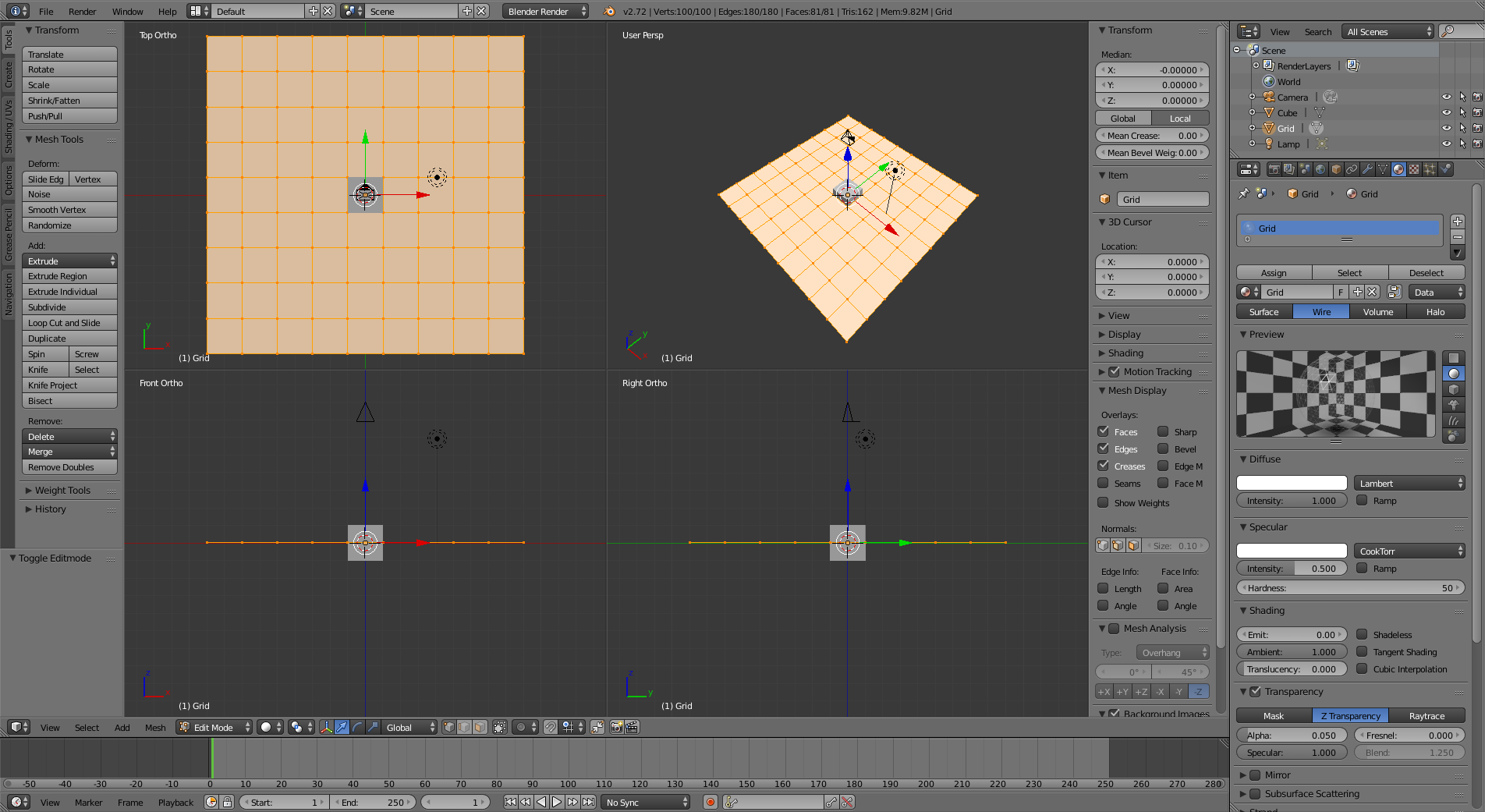
As far as I know, Blender doesn’t have a Grid System like DeltaCAD 3.0.
In the N panel of the 3D view you find Display -> Grid settings:
Note the scale length in the units scene settings in blender might be problematic for precision modeling. It’s better to keep it as is (at value of 1). I model in meter dimensions, because in mm you’ll have resolution problems and some addons might not properly handle the units settings scale length. Beware of it! Can still set the scale length unit setting later which I recommend because while scaling all objects at once is possible, it’s also problematic, especially if animated, constraint or more.
Also I think Sergej recommended to use physics simulation with meters. (Not sure about it.)
I finally got to watch the entire Jonathan Williamson video after many Real Life distractions.
As a Draftsman, it is funny watching him create the Dimension Lines and Arrows and Dimension Text; because, he is clearly an Artist who has no idea of what he is doing with the Dimensions.
Still…The Blueprint & Grid System is a good Starting Point for Manually Creating A Blueprint.
Jonathan’s Knowledge & Skill with Blender is Master Class.
As far as Creating Blueprints is concerned, as a Draftsman it is more important to establish a “Page Setup” Document that can be applied to various Projects.
I have created my own Literary Project “Page Setup” for MS WordPad; and, VBScript “Page Setup” for Visual BASIC Script Coding on MS notePad; and, I have my various DeltaCAD “Page Setup” Files; although, with DeltaCAD I have to reset the Grid Spacing Settings to match the “Grid Layer”.
With Blender, I would create a “Blueprint” File; then, SAVE it as a “Page Setup” Project; then, use that “Page Setup” Project for creating Blender CAD Projects.
With Jonathan Williamson’s “Create A Cool Blueprint”, Creating the Gridded Background would be the First Priority then creating the Gear to align with the Background Grid is how a Draftsman would approach CAD Projects; because, “Scale is everything”.
It is my understanding the USA International Businesses like Boeing have converted to the Metric System; because, the Metric System is the International Standard.
I am not a Businessman; and, I am not affiliated with International Businesses; thus, as an older USA Civilian, I prefer working with the Imperial System for my Personal Projects.
If I were involved with International Businesses like yourself; then, I would probably be working with the Metric System.
@Q-Lab
I have been using blender as a CAD program for years. Most users of blender prefer to sculpt models using the 3D viewport and do amazing work. I use it a bit differently than most users in the sense I use Python scripting to make my models. I use a micrometer to gather my dimentions and put those dimentions into the python script.
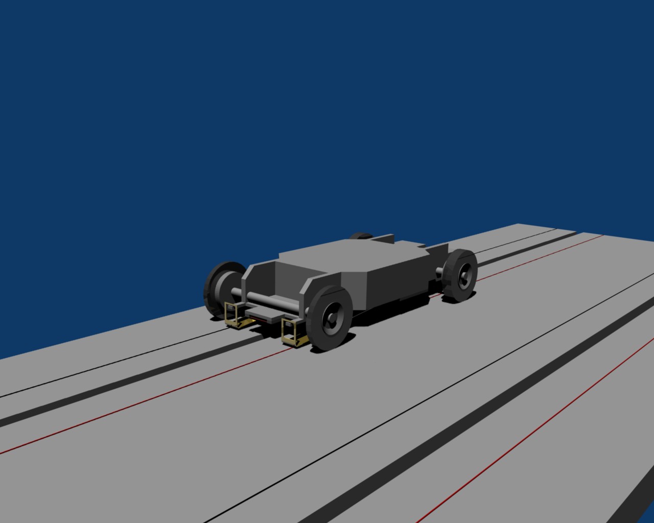
Here is a render of an HO Scale Slot Car chassis and track I still have yet to finish that is completey scripted:
Every piece is a seperate model. I think you might be able to do much the same thing with satisfactory results. This is accurate to the 1/1000 of an inch, even though my Blender settings are metric and I used mm to enter each point/vertice. My referance material were the actual toy and US Pattent documents. This is an accurate (almost completed) replica of Aurora Model Motoring designs which are in Public Domain as of 1983 when they filed Bankruptcy. The only thing left to be completed are the gear plate and motor, and making the hole in the center of the chassis for the motor.
So I think you can get a better CAD like feel if you learn how to script in Python and make models that way.
I am familiar with GW-BASIC; but, Y2K Computer Systems won’t operate GW-BASIC.
Anyways, GW-BASIC is too weak for the kinds of Computer Programming Projects that I want to do; and, I haven’t found any Y2K Programming Languages that allows me to do Graphics Programming like I could do with GW-BASIC. Everything is OOP now; and, Moition Graphics are controlled by Graphics Applications like Blender and Game Maker.
Right now, the only Computer Programming Language that I am “playing” with is Visual BASIC Script; and, Text Graphic Control is weaker than with GW-BASIC. I am limited to doing Input Box & Message Box Text Graphics for my Computer Programming Projects.
I Uploaded a Blender File accidentally in one of my earlier Postings; because, I thought it was an Image File.
I made a Video Recording of my Tonight’s Session. However, my Video Camera doesn’t have a DVD Driver to put into the Computer because my mother threw away the Video Camera Packaging that contained the DVD Driver.
Also, my Video Camera is a Cheap Model that runs on AAA-Batteries; thus, Video Quality is low.
I am thinking about using my mother’s Video Camera to record the Video Playback on my Video Camera to upload my Tonight’s Session.
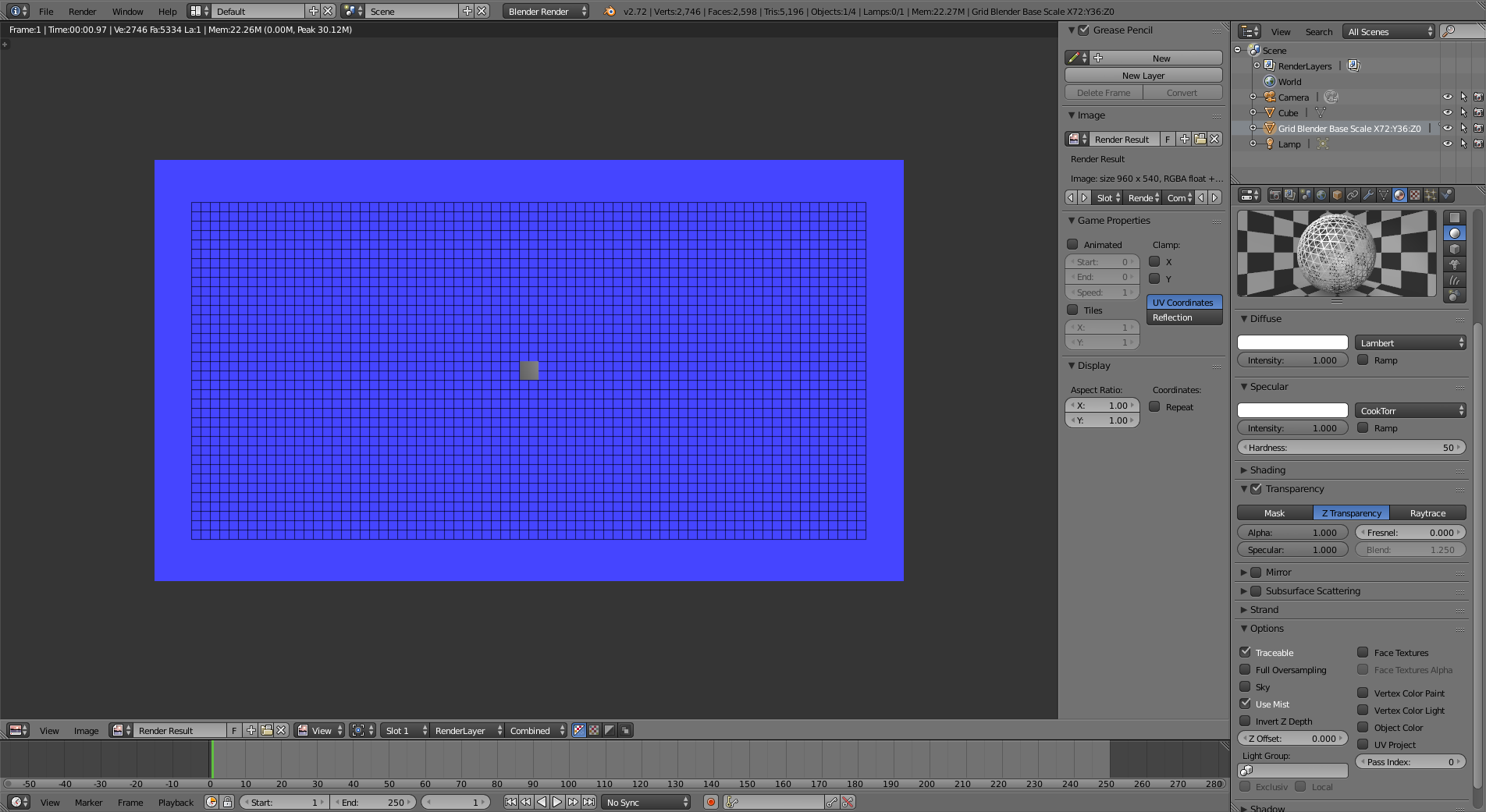
I just opened my GridSetup file; and, it was in Camera View.
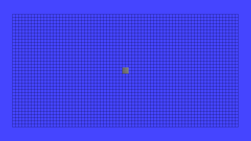
I looked at the Object Mode and Edit Mode for the Grid; and, they hadn’t changed. Then I Rendered the Image; and, the Line Thicknesses was the same as my Previous Posting.
I didn’t SAVE initial Image thinking that I could get back to it.