DeltaCAD 8.0 looks like a very good CAD Application; but, I’m not going to Update DeltaCAD 3.0 to DeltaCAD 8.0; and, I’m not looking for a new CAD Application at this time.
I am no artist; but, I could probably attempt to hand draw a Human Head with the features that I am looking for.
I am just using Computer Applications instead of the old Pencil-N-Paper Technique for creating the Human Head with the features that I want. And…I am not a Computer Geek in terms of utilizing Computers beyond Typewriter Text Document Projects and Video Gaming and Computer Programming Projects (GW-BASIC is what I do know; but, I am working with Visual BASIC Script because I don’t know any other Y2K+ Computer Programming Languages as an Amatuer Hobbyist Computer Programmer)…LOL.
Instead of using DeltaCAD, I could try Drafting By Hand. I do have the equipment and paper; but, I don’t have a place to do, and stow, any Drafting Project.
The Blender Website has alot of Tutorials concerning Human Head Topology.
I am very new to Blender. I tried to do my Blue-Yellow-Red Monkey Layer Test; and, failed because I didn’t know how to color the Monkeys.
I have been looking at the many different Tutorials on the Blender Website; including, the one that showed how to separate three Monkeys into three separate Layers.
I just need to work at using Blender more than what I am.
don’t think in terms of measurement more like proportions in blender
get the shape you want then after you can always re scale it to what ever you want
Just a note but 3d modeling software is very different compared to CAD,it’s easy to move from 3d modeling to Cad but the other way around is much harder.
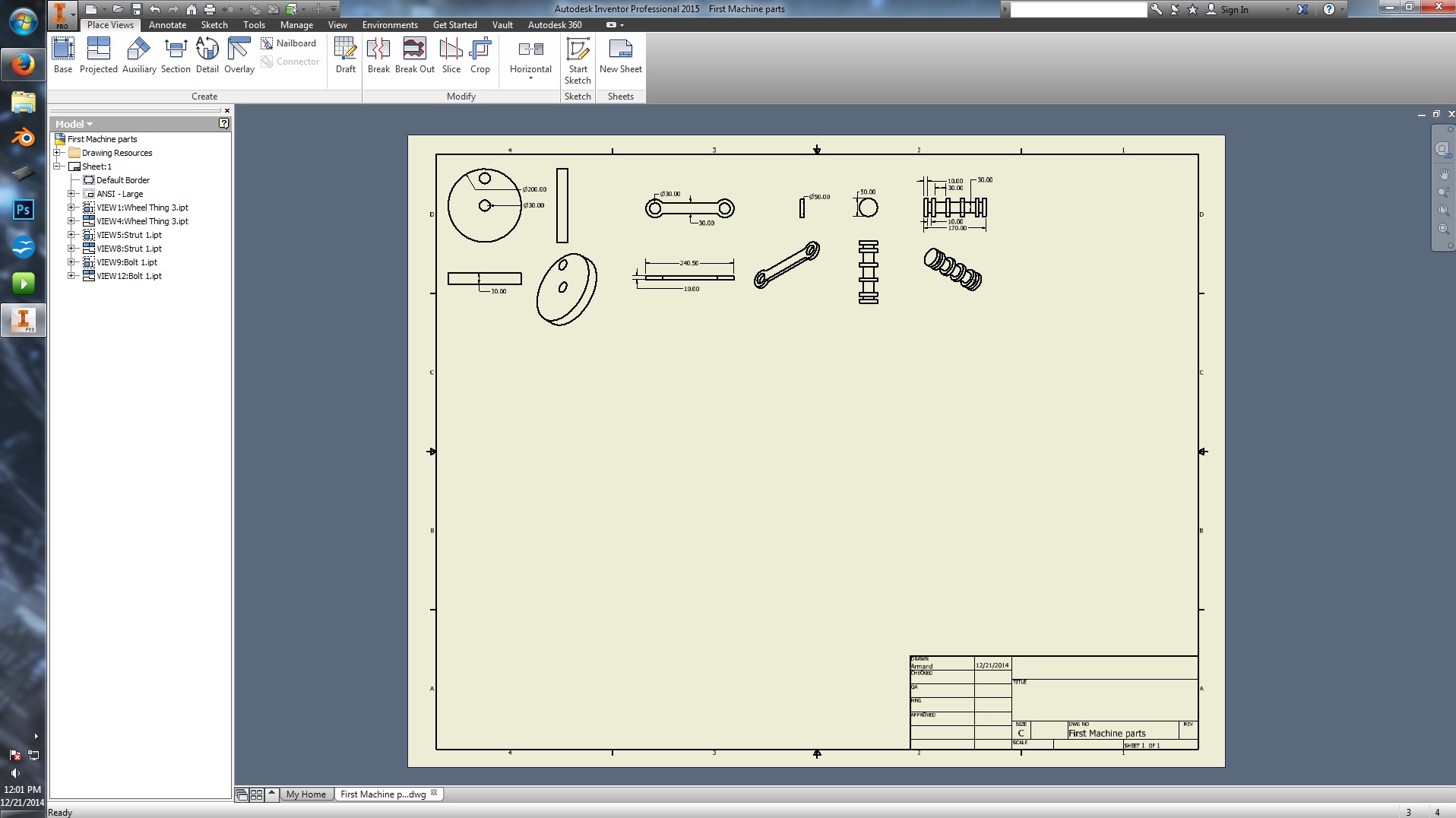
I’ve just started with CAD but this is what my .dwg file looks like:
I haven’t seen that Drafting Paper Style, and Drawing Layout, since my Collegiate Drafting Course back in the 1990s; but, they were done on Real Life Paper; and, drawn by Real Life Human Hands.
Thus, with CAD, you don’t have to contend with creating and erasing Construction Lines the way that Hand-Drawn Drawings have to.
I have to agree with your assessment concerning 3D Modeling Software and CAD Applications.
My brother said that Blender doesn’t do Scaled Images; that is, 1" on the Computer Monitor = 1" in Real Life Printout Measurements; because, the Printout Image is based on the Camera View. He also doesn’t work with the Quad-View.
His style of working with Blender is very different from my style of working with Blender.
I am thinking that if I have the Camera View doing a Head-On Face View; then, I would be able to create a Grid Image like my DeltaCAD “Grid” Layer.
I have no idea of why I can’t Download the Image that my brother created into this Posting.
I’m still trying figuring out what you want to do.
From the screenshots i’ve checked on DeltaCad,it looks like a type of Blueprint Cad program.Although blender can create blueprints and drafts with addons,it’s not exactly the best application for the job.
Also,image scale can be changed in the render tab under dimensions.I think it’s set by default to the monitors resolution.
Also,my grid system is working fine from all num pad views.Do note that the size of the grid will change if you zoom in or out (obviously).Wireframe can be toggles off and on in a window by pressing Z.
My latest Posting Image is of 3 Circles in the Top & Fornt & Right Side Views. Each Circle is Imperial 4" Radius; and, Imperial 4" away from Origin (x=0,y-0,z=0).
The Blender Printout on Letter (8-1/2" x 11") Paper with the “Scale To Fit The Paper” Option Deselected results in the circles being Imperial 4-1/4" in diameter.
okay…I see the error in my drawing. The Circles are 8" in diameter.
Back to the Drawing Board.
All I have top do is change the Camera View for the Printouts.