Painted metal works a bit different because here you have to use the properties of the paint rather than the metal and paints are often composed of several layers. It depends if the paint is transparent or compoletely opak. If it´s opak you can probably in most cases just create a dielectric shader.
If it´s transparent you have to mix the dielectric paint shader with a metal shader discussed in this thread. Dielectric shaders are discussed in the beginning of this thread.
I´ve never made a pbr car paint shader with this method but I´d try to blend:
primer -> rough dielectric material
metal layer -> shader discussed in this thread, perhaps blended with a diffuse shader, low roughness
metal flakes -> shader discussed in thread blended on top with tiny voronoi map, very low roughness
clear coat -> probably some standard glass shader or something like that.
Blend all of them together using mix shader nodes at different values.
Here is the file.
I´m afraid the shader is a horrible mess because I just quickly plugged it together for this test. There´s a group called “bump” on the left which contains, well the whole bump stuff. The mess on the right mainly adds some dirt to the seams with the pointiness value.
You´ll have to put an hdri into the background shader.
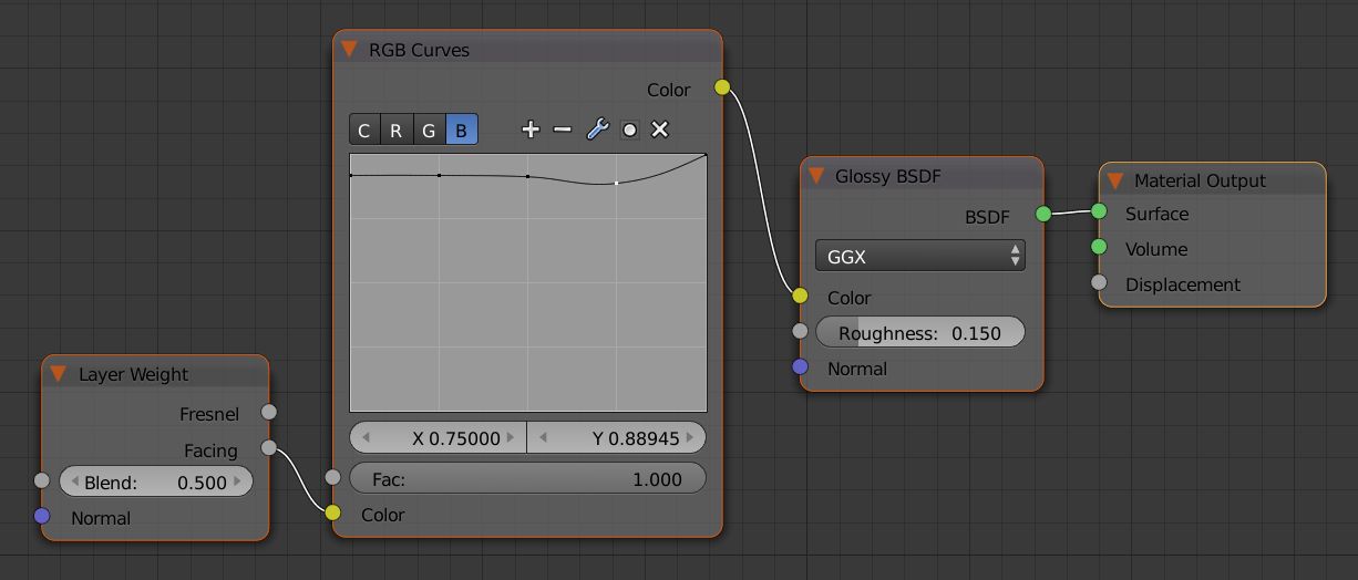
Only blue channel shown. Red and Green channels must be set up according to refractiveindex.info
Here is *.blend file pbr-materials-test.blend (720 KB)
You have in the material a couple of diffuse shaders with colour 0,0,0 and some roughness. If I unplug the shader I can’t see any difference. I’ve always thought a diffuse shader completely black would have no effect (other than slowing down your render).
Promising technology. I always thought that Cycles is at the top of physically based rendering, but now i see that LuxRender and Octane Render is probably more advanced.
I agree that the result would be the same, but AFAIK the shader needs nevertheless to be evaluated for every shading point, unless there is some code optimisation skipping the shader when the colour is set to 0,0,0. Do you know if is it so?
ok i’ve tested it a little bit and it seams it doesnt work for diffuse 0,0,0 but it works for emission and for other nodes background shader etc. (nevertheless with rgb 0,0,0 it renders a lot faster than rgb 0.004,0.004,0.004 for example)
Yes, I did a test myself, just with the diffuse node. The difference is noticeable.
It would be nice to know exactly which nodes have such optimisations: I use a not-so-new laptop, and every little bit helps!
I’m having a hard time understanding that math. Could you explain it in some more depth. Using 0.92545 as the value from 30 degrees non-polarized?
So 90 = 1, I get that.
And 30 would then = 0.92545 right?
But then I get lost on the next three steps in converting those values for Blender’s curve… Also, once the value is found, I just plug it as a point in an RGB point into the Blender curve right?
Trying to construct physically accurate copper myself so I can understand this stuff.
So these curves are the color wavelengths right? These create the color of the material? What about Fresnel? Do these go into Fresnel as well? Further, facing would work better would it not? Also, wouldn’t I need to hook up the facing/Fresnel to a roughness control to make it truly accurate?
Also, this renders slower?
It appears I can put the values in more or less directly into blender…
Blender’s curve graph goes to 1 and 1 on both X and Y. The wavelength graph on that website goes from 0 to 1 on y and 0 to 90 on x.
Converting the angle to an integer, it essentially goes from 0 to 0.9, and if you multiply any given angle’s integer by 1.1112, it will stretch the x value out properly for Blender’s graph which goes to 1 with a tiny, tiny margin of error.
So 45 degrees would convert to 0.45*1.1112 for 0.50004 as the x value for Blender, and the y value would be the same, 0.92336. Plotting about 10 of these accurately recreates the curve with a small margin of error.
John Lancaster, Layer Weight -> Facing yields a (1 - dot(normal, incoming)). Dot product is a cosine of the angle between those vectors, 0 being 90 degrees, 1 being 0 degrees. Because we get 1-dot, 0 will correspond to the left margin of the graph (0 degrees), 1 - to the right (90 degrees). So, if you want to be “precise”, calculate cosines of (90deg minus angle in the graph), and substitute results for X values in the RGB curves. Or you can eyeball it roughly (e.g. 45 degrees -> X = 0.5, even though it should be around 0.7, etc.). For mapping use the non-polarized (green) curve, wavelengths for R, G and B have been mentioned in this thread, roughly they’d be 0.65, 0.51 and 0.44 respectively.
Meanwhile, I’d like to say thanks guys for this interesting thread
@@John_Lancaster
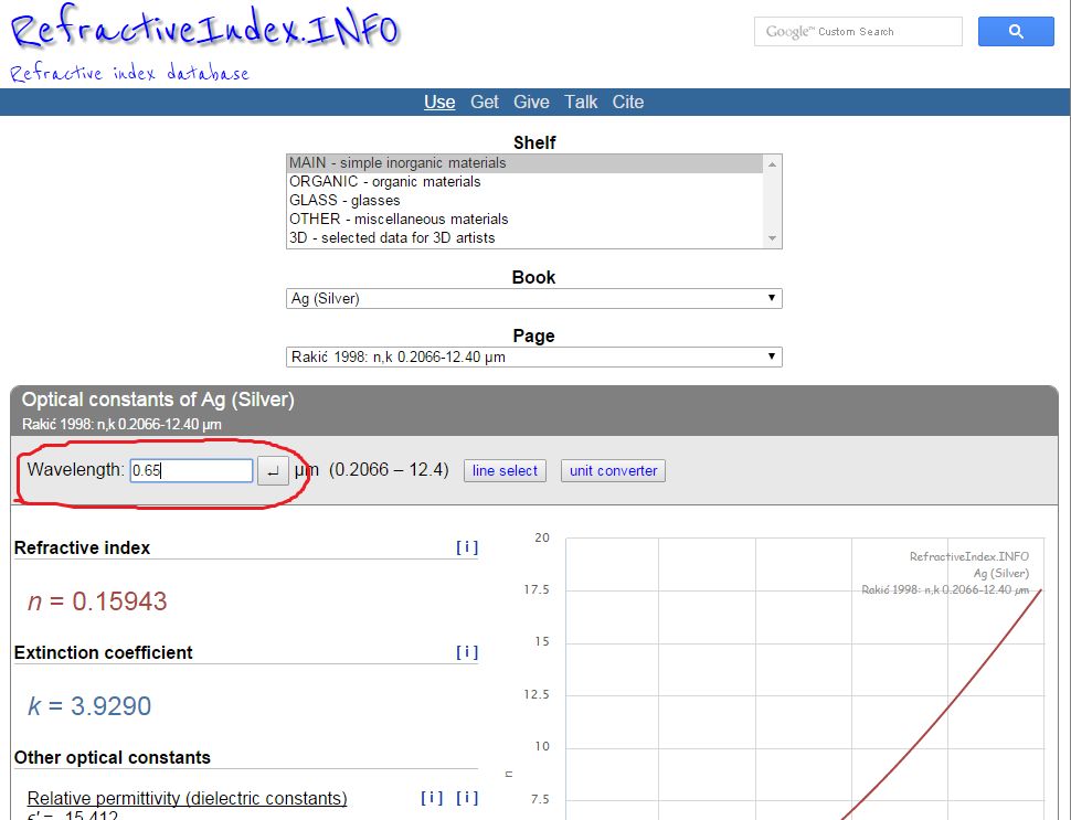
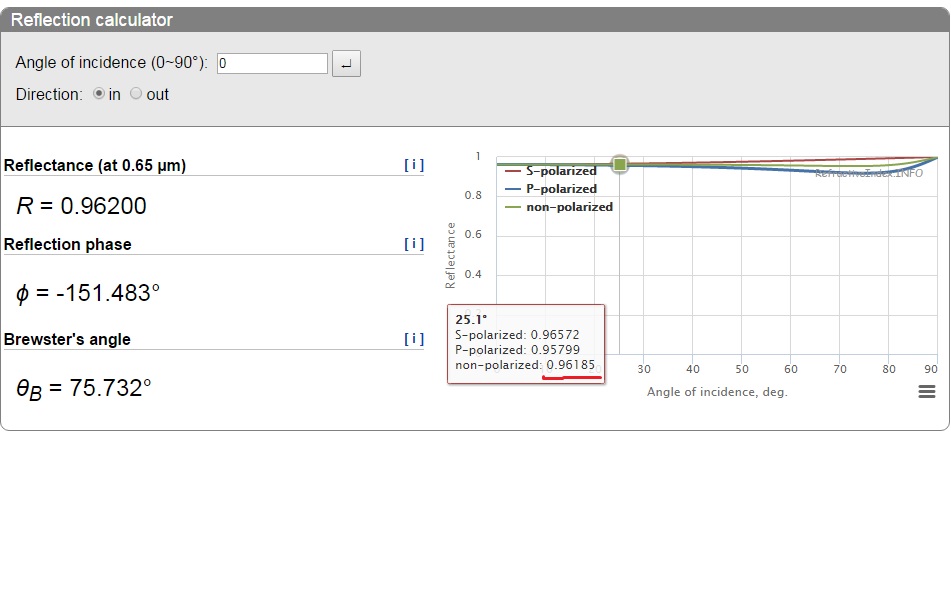
Sorry, i didn’t see your mesage. I also tryed to convert values from refractiveindex.info into blender, but gave up after some non-understandable results. So i put numbers from refractiveindex.info into blender RGBCurve node directly. Say, i choose Argentum, then type wavelength 0.65 (red channel) and see that at 25.1 degrees it has 0.96185
Then put this value in RGBCurve node, in Red Channel. Then setup another points for curve (50 and 75 degrees accordingly).
The same algoithm i use for Green (0.52) and Blue (0.44) Channels


 D
D