Nice.
I think this only works for dielectric materials, though, because calculating the reflectance of metals with Fresnels equations requires the complex IOR and the complex IOR requires the absorption coefficient.
Lumpengnom it is a factor! (fac * closure + (1-fac) * closure)
Oh… :spin: …Thanks for correcting me. Sorry Lumpengnom. :o
Now am lost again… Where can i get more info? I am self thought and have no proper foundations… so am always falling and rising.
burnin just look at the osl shader code from cycles 
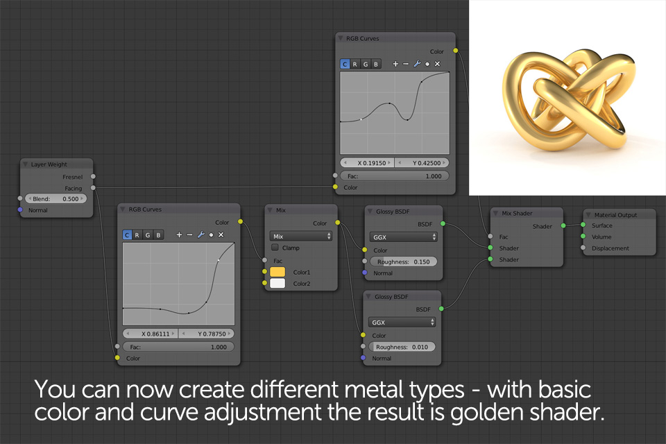
@lumpengnom (and all the others of course :)) here are 2 different fresnel conductor nodes (one with artistic controls based one this here link ) let me know what you think
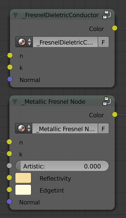
edit: blend update 
Awesome. Thank you.
And thank you for linking that paper.
I´ve been researching this Fresnell stuff on and off for over a year now and was often rather overwhelmed with applying the pure physical explanations to shaders. This paper helps a lot in explaining everything on a deeper level.
BTW, here is a nice database for different materials with IORs and Extinction Coefficients at different wavelengths. Some are proprietary and you have to pay to get the full information but a lot are free.
have you tried it lumpengnom? a nice render like on the first page would be nice! 
@burnin
I was ill and can’t answer sooner. Thank you, it seems i understand, but it is getting rather complex for me now.
Here is my algorithm of work, as i understand:
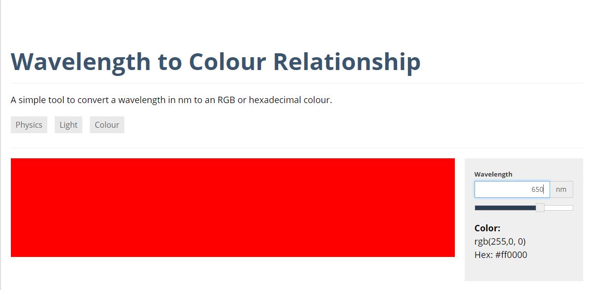
- I download “Spectra” program (or some visible light wavelength book) and see wavelength of red, green and blue
color. - Then i just pick wavelength values for each color from “Spectra” program, put theese values in
http://academo.org/demos/wavelength-to-colour-relationship/ and tweak them until i get pure green, pure blue and
pure red in RGB, right? That is why you use 0.51 for blue instead of 0.52. Because 0.52 is not pure blue in RGB
color space?
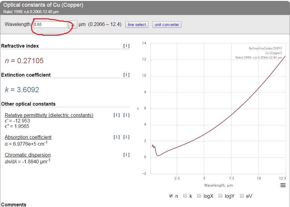
- I go to refractiveindex.info, choose “Simple non-organic material”, and then “Copper”.
In “Optical constraints” block i set up wavelenght to 0.65 (our red color)
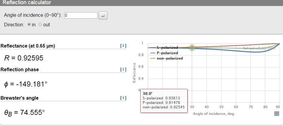
and scroll down to “Reflection
calculator”. In “Reflection calculator” block i pick non-polarized curve and point my mouse, for example, to 30
degrees where i can see that non-polarised curve value is 0.92545
- I adopt this value for blender, using cross calculation
90 degrees = 1
30 degrees = x
90x = 30
x = 30/90
x = 0.33333
Since this curve is more curved at the and I also recalculate for 60 degrees (0.33333), 70 degrees (0.77777) and
80 degrees (0.88888)
The same operations like in 03 and 04 i do for green and blue colors.
I need to clear this out before i start set up nodes in Blender
P.S. Looking at your node setup i don’t see any 0.27777 at any point of any curve. Where i need to put may calculated values?
@Lampengnom
Your node setup seems more understandable to me because it resembles http://www.chocofur.com/6-
shadersamptextures.html with which i am already familar with.
Why you need diffuse shader for metal? Guy from http://www.chocofur.com don’t use it for metal shader
@All It would be great to precalculate automatically most common materials in the way you did and create “PBR Cycles Materials Library” which can be easy to use for every Cycles user. I’m sure it will provide great help for artists struggling with node system.
Well, i don’t see any point in recalculating values from refractiveindex.info since burnin node setup uses the same values as they represented at refractiveindex.info
I’m totally wrong? Guys, can you help me clear this out?
Yeah, no point, just an approximation with this approach… since cycles is not “physically true light simulator”, all we do is seek the pleasing & plausible imagery.
Here is what i have now
node setup
Can someone explain why using noise texture with color ramp is better than just using roughness in Glossy node?
what do you mean?
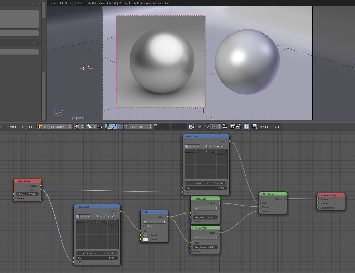
Yes, it works great. Here is a comparison. My shader on the left and your node group on the right. They both use slightly different wavelengths, yours being the physically correct ones. Only thing I did was change the roughness to 0.12 from 0.05.
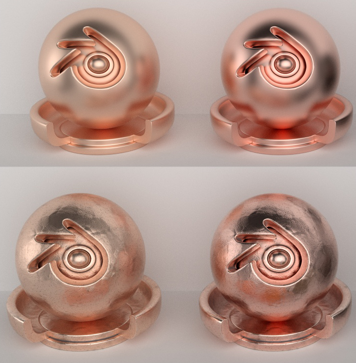
Looks unnatural… using reddish HDRI?
example photo:

@lsscpp
I talking about node setup by burnin
[ATTACH=CONFIG]410590[/ATTACH]
As you can see he use noise texture and color ramp for roughness.
I can’t understand the point of it. I understand why we use noise texture (still don’t understand why we don’t use roughness in Glossy shader), but what for we use color ramp?
color ramps modulates the noise input. It re-maps the 0-1 input to whatever you set with those markers.
In this case it inverts blacks and whites and gives contrast. (0(black) is white and vice-versa, and the progression is shrinked in the middle). Plugging this into roughness gives noticeable variation in the roughness of the glossy node. just unplug it to see the difference
@lsscpp Thank you, but why not just use Roughness?
To tell the truth i don’t see any difference between plugged and unplugged Noise texture. May be my monitor is bad, or my eyes.
Hey guys, I just read all the thread but I’m a little bit lost here… I hope someone can explain this a bit better.
Why are you connecting the curves node to the color input of the glossy bsdf? If that’s the physically correct way to use it then how I can create colored metals…?
I’ve been checking out the videos of Cynicat Pro, and while he states that his solutions are not 100% correct they seem to give pretty good results for quick metal shaders; as well as the ones posted on Chocofur, but they use the curve as a factor to mix shaders and color mix nodes, not to directly control the color of the material…
So how should I combine the information you’ve posted so far with the mentioned setups? What would be a proper way to create good PBR metal shaders?
EDIT:
This is the explanation to use the curves from refractiveindex.info in Chocofur:
Without getting into physical details, there are websites out there describing this phenomenon and the one you should definitely check is: refractiveindex.info. What you can find there is the “Reflection calculator” showing the actual look of reflectivity curve for every material you choose. The curve is split to RGB values and since re-creating this in Cycles would be too troublesome (yet possible), I usually try creating my own, similar looking curve, averaging all three color channels. The curve should be used as a mix input for 2 colors - white for very low angle reflections and any other color on the opposite site - depending what kind of metal you’re trying to create.
As he puts it, the curve should be used as a mix input for 2 colors… So again, what’s the reason to connect the curve to the color input of the glossy bsdf?
Based on that, wouldn’t this be a “good enough” approximation to aluminium…?
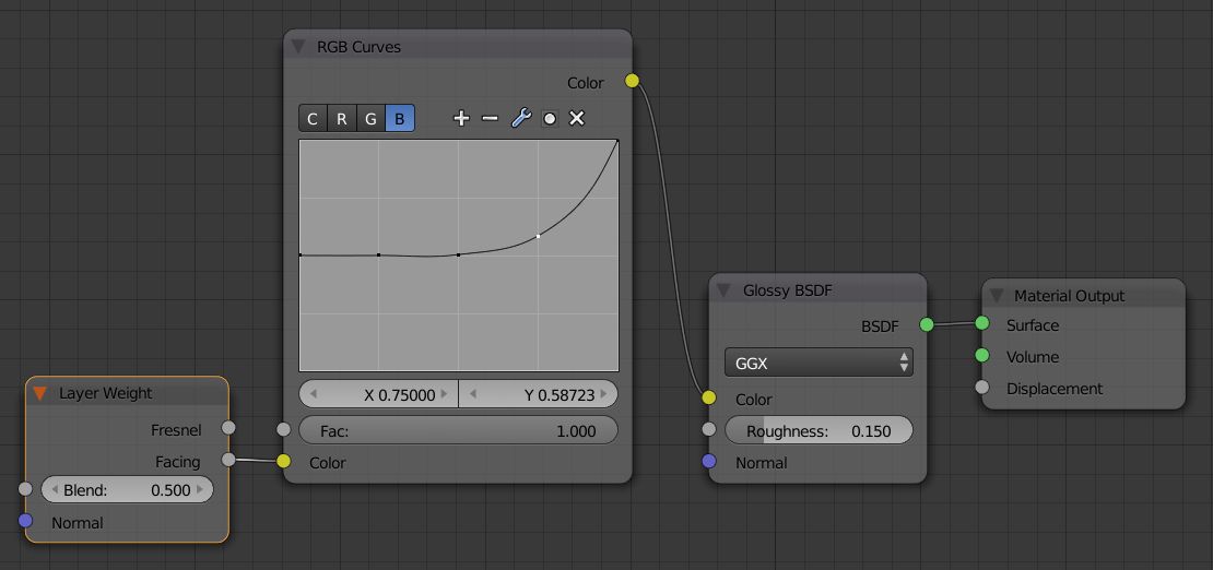
The curve node actually has four different curves. One for all three channels, one for Red, one for Green and one for Blue.
Some materials reflect different wavelengths of light differently. So if a white light ray hits the material it is “split up” into red, green and blue light (not really but it´s enough to simulate the effect on a computer screen). The red part of the light is reflected differently than the green light and the blue light is reflected differently as well.
We use this fact combined with the R,G and B channels of the RGB Curve Node to simulate the splitting process. Note that the combined curve of the curve node is not changed at all.
The layer weight node tells the shader what to do at which viewing angle. The curve node changes the way the layer weight node displays the reflection. Since the curve node uses the three channels R,G and B it changes the way the layer weight node works differently for each color.
The curve is then plugged into the color of the glossy shader node. The color of the glossy shader node is basically nothing else than the reflection color. A glossy shader node dosn´t have a diffuse component for example. The layer weight and the curve node tell the glossy node with witch strength it should reflect which color at wirch viewing angle.
The node trees you posted don´t seem to make any sense to me when it comes to physically based materials. That´s just not the way it works in real life. Doesn´t have to be a bad setup but it´s got nothing to do with physically based materials.
<edit>That´s the way metals get their colors. Most metals don´t have a significant diffuse part and get their color mainly from the reflection.</edit>
It´s a black and white studio HDRI. There are a couple of other objects offscreen, though, some are red. I´ll do another test tomorow without these objects.
Thank’s for your explanation @Lumpengnom, it is a bit clearer now, but then how I would go about creating a car paint shader if I want it to be a physically based material? Or any painted metal that needs to have a specific color?
Ahhh… OK, that explains it. No problem. It’s also visible in photo (reflections of hemispheres & internal/inside of hemispheres tinted red). Nice work on the noise BTW ![]()
(care to show how it’s done?)