Customization questions from a Blender-curious 2d/3d artist.

It’s not there, you have to add it. Correct location in the input options was mentioned under the screenshot “Adding a hotkey under 3D view -> Mesh to toggle limit selection to visible option”

Edit: Ah, you mean after adding it. Not really a good way. Probably best to know it’s a mesh edit mode toggle and then search for the hotkey and look under mesh category.

Ok, let me recap to see if I am getting this right. Let me know if I am off-base.

  • If I understand correctly, the input categories are actually the different contexts that Blender operates with. (Window, Screen, View2D, 3D View, and so on). It makes sense, as this is the core of the context-dependent nature of the Blender hotkey system. From there, it follows that I would need to create this hotkey under 3D View > Mesh, since this is the context it is designed to work under (mouse hovering over the 3D viewport, and model in Mesh edit mode). I am correct in my understanding ?

  • Still, how do you go from knowing that the python command is “SpaceView3D.use_occlude_geometry”, to knowing that the context attribute is supposed to be “space.data_use.occlude.geometry” ? I obviously don’t want to have to ask a similar question on the forum every time I need to create a hotkey for a function that is not in the default list …

I hope this makes sense !

  1. yes

  2. don’t remember exactly but looking around, going to guess I found it from the UI python file by right clicking on the button -> edit source, which puts it in the text editor list and can open it there


It goes to the line where the button is automatically (highlighted). Says view and use_occlude_geometry. Following there to line 54 it checks view.viewport_shade. Then up on line 32 it says “view = context.space_data” and because the hotkey is a context toggle, tried space_data.use_occlude_geometry

Select the two edges and press the W-Key (“Subdivide”). A new vertex is placed at the middle of each selected edge, and a new edge is formed between the new vertices.

Thanks JA, that makes sense - this is exactly the information I was looking for, and something that I think should be covered in Blender introduction tutorials. Since the program relies so much on the default keyboard shortcuts, I think it is very important for users to understand how to create the missing ones, and it would come with the added benefit of learning how the program actually operates under the hood. This was the very first thing I learned on my first day of using Maya a few years ago - the TD at the studio I just started at took me through the steps required to identify the mel commands triggered by various UI elements, so that I could make my own shortcuts without having to ask him. I was quite surprised later on when I noticed that this very important part of the program was hardly known by many users. It certainly wasn’t their fault, but it says a lot about the teachers they learned from :).

Matsuiko : I just found the global dissolve command. It’s called “dissolve selection”. I still have to find the global delete tho.
http://img.photobucket.com/albums/v242/pior_ubb/2014-11-0402_29_43-BlenderUserPreferences_zps708c97b9.png~original

See360 : perfect, that covers it. It’s quite interesting actually - I was already using the Subdivide command to add a vert in the middle of an edge but I had no idea that it also doubled up as a connect tool when performed on multiple edges at the same time. This is certainly unexpected, but I can see it being useful. Thanks !

Here is a video showing my texture removal issue in detail as explained on page 1.

- Texture and material removal

This last point has been really puzzling me. I imported an .OBJ mesh and was pleasantly surprised to see that Blender picked up the corresponding .MTL perfectly ; the model appeared with all its materials properly assigned. However I am running into an issue which I think is a bug. When I duplicate some faces from this model to then work on a separate part (for instance, duplicating the surface of a shoulder to start working on a shoulder pad), I am then unable to remove the texture from that newly created mesh. Now I am not fully versed with the unique Blender approach to materials (they seem to be instanced and part of the models themselves rather than being pulled from a scene library, if I am not mistaken) but I think I took the necessary steps to remove the texture from that part - yet it still shows.

[edit] Okay, it took about 4 hours of research and asking other Blender users, but I finally figured it out the issue ! It is actually a rather odd behavior : in Blender if an object has any kid of UV data, it is impossible to display this object with a plain colored material when the viewport is in “solid” mode. Instead, the model shows up as white even if all the faces have their material assignments removed. The data that needed to be removed was under Properties > Data > UV Maps.

What is the best way to escalate this problem to the devs ? I am not sure if this should be filed as a bug or as a feature request, but it certainly is an issue …

Personally i just use subsurf with supporting loopcuts to smooth surfaces or edge crease for low poly.

…[deleted]

As mentioned in that thread, the Auto-Smooth setting combined with sharp edges may work: you shade all faces smooth, enable Auto-Smooth with 180 degree angle in object data, and then mark edges that need to be sharp (select edges, Mesh -> Edges -> Mark Sharp). I’m not sure if or how well this is respected by current exporters though.


Awesome, a lot of great information everyone. I appreciate it !


- On lowpoly hard edges marking

DCBlood : Unfortunately the subsurf approach is not a viable option in the case of very low resolution game models, but The Mark Edges function seems to work - I just wasn’t aware that it requires the object data to be set to autosmooth as Stan explained it. Once I enabled this everything seemed to be fine.

http://img.photobucket.com/albums/v242/pior_ubb/2014-11-0417_49_29-Blender_F__Dota2art_Bloodseeker-DropsofAncientCrimson_Blender_BS_blockou_zps157e3210.png~original

Now of course I have to run some extensive tests to see if the OBJ, FBX and SMD exporters actually support it.

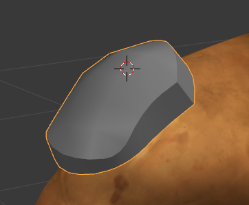
On a semi-related note : is it possible for the “Subsurf” subdivision modifier (or any alternative smoothing tool for that matter) to actually use this marked edges data for topology subdivision ? I am of course aware that there is a dedicated edge creasing function designed to finely control edge tension, but being able to control subdivision with very straightforward subdivision creases displayed on the lowpoly model as hard edges is a very valuable approach too. As demonstrated here : https://www.youtube.com/watch?v=87I8FpXn3Yc . Note that such marked edges behave in a slightly different manner from “regular” edges creased to a high tension value.

This is of course mostly useful for a certain style of highpoly models as it lacks the finesse of manually inserted control loops, but it can be a huge life saver in tight production schedules (talking from experience here !). I suppose that such a feature could be added to the Subsurf modifier later down the line … Anyone knows if this is being considered by the devs ? And if not, what is the proper channel to escalate this suggestion ?


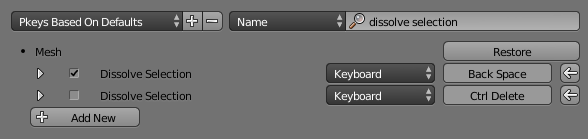
- On edit modes and component deletion shortcuts

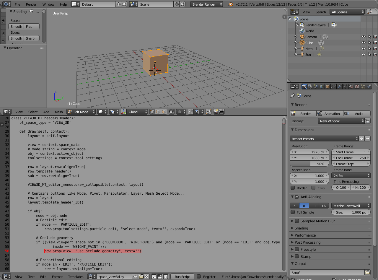
Thanks for the info - it seems to confirm that this is indeed very doable. Unfortunately I do not have the knowledge required to extract such scripts from this Pie add-on ; I fully understand the concept but I am not familiar enough with Python and file sourcing in Blender in order to attempt that. Maybe later ! The relevant Mesh selection scripts seem to be located at line 966 of the pie menu script (https://github.com/pitiwazou/Scripts-Blender/blob/master/Wazou_Pie_Menus#L966) but that’s about as far as I can go since I do not know how to create UI items calling such code. Same goes for a unified Delete command.

(In mel and Maxscript this is all done by pasting code into a script editor window and running it from there to test it out. If successful, the block of code can then be used in the hotkey editor and/or the UI editors. Is there a similar approach in Blender ?)


- On project folders

Good to know that relative file paths are an option ! If they work as I expect them to they would totally cover the functionality of project folders. I will test all that further later.


- On texture preview removal

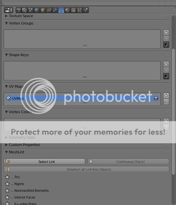
This behavior still puzzles me but at least I now know how to disable it ! I am talking about the fact than an object displaying a texture in Solid viewport mode needs to have it’s UVs channels completely removed from its object data in order to accept a plain color material - removing the image from the image editor doesn’t fix that, as the faces just turn white. I have never encountered such a behavior in any CG software before and I am quite confident that this is a bug … or at least, a UX/design oversight :slight_smile: Same goes for the material preview spheres not being consistent with the look of a previewed textured model.


Thank you so much guys for the info guys, I think I now have everything I need for my current tasks. I still have a few questions regarding object pivot positioning as well as object transformation along an arbitrary axis, but this is not affecting what I am currently working on. More on all that later !

No, you’d have to do this with creasing, or in some isolated cases Bevel modifier controlled by bevel weights or a vertex group may help.

Anyone knows if this is being considered by the devs ? And if not, what is the proper channel to escalate this suggestion ?

Currently there’s an ongoing project of integrating OpenSubdiv into Blender, so I wouldn’t expect any changes to subsurf until it’s completed. To address developers, you can use the mailing lists or IRC (links are on the wiki).

(In mel and Maxscript this is all done by pasting code into a script editor window and running it from there to test it out. If successful, the block of code can then be used in the hotkey editor and/or the UI editors. Is there a similar approach in Blender ?)

Blender has a Text Editor from which scripts can be run. It also comes with a bunch of templates to quickly mock up operators or menus (check its Templates menu).

I am quite confident that this is a bug … or at least, a UX/design oversight :slight_smile: Same goes for the material preview spheres not being consistent with the look of a previewed textured model.

Three out of three wrong :slight_smile: Well, maybe 2.5, not three.

First of all, look at what the tooltip for Textured Solid checkbox tells you: “Display face-assigned textures in solid view”. This is useful to preview your UV textures without the need to create a material and add a texture there. It may be argued that in the absence of assigned image it should not override the material color (thus the 2.5 above), but I wouldn’t hurry with branding this a bug, as it may as well just be some technical limitation.

This is why the material preview is also different: Textured Solid setting doesn’t change the material in any way. For previewing materials specifically, it’s best to forget about Textured Solid setting altogether, and use Material view (you’ll need lights in your scene, or if you want to view plain colors without shading, enable Shadeless property for the material).

Some great insights again ! Very useful stuff, thanks man.

I am actually already back with another question.


- Dynamic mirror instancing of multiple objects

Is there a way to assemble some objects together and apply a dynamic mirror to such an assembly of objects ? With the ability to later add new objects to this assembly, with the mirrored duplicates automatically showing up within the instanced mirrored copy. It would also allow the user to freely transform objects from the original assembly and have their mirrored counterparts update accordingly. Like this :

I already tried a few things to achieve this desired setup. The first one was to use the group function (green outline) but it doesn’t seem to create a group in the usual sense of the word, but more of a selection set - this is a useful feature, but not what I am looking for.

The second approach was to use parenting : that is to say, parenting all the desired objects to a master. I also tried using a helper object as master (an “Empty” in Blender terms), as well as a lattice, followed by duplicating all the objects and performing a Object>Mirror>X Global on the master. The lattice worked the best, since I can edit its vertices for visual clarity.

However (and quite logically …), transforms applied to the original elements of the assembly are not getting carried over to the other side. It makes sense, since the only actively mirrored object is the lattice itself, and not its children. Ideally I would like to be able to transform any part of the original assembly and have its counterpart on the other side update automatically. Is it possible ?

http://img.photobucket.com/albums/v242/pior_ubb/2014-11-0500_27_24-Blender_F__Dota2art_Bloodseeker-DropsofAncientCrimson_Blender_BS_blockou_zpsbcc30e6e.png~original

For reference, in Max this would be achieved by :

  • Selecting all the desired objects
  • Creating a Group entity from them
  • Applying a mirror modifier to this Group object, or, creating a mirrored instanced copy of it.
  • From there, the user can “open” the group (that is to say, accessing its contents it for editing) and all the changes within it get applied to the mirrored copy.

I am confident that Blender has a way to do that - but I just couldn’t find it even after quite a bit of research. I wouldn’t be surprised is there was a script out there doing all these operations in just one click easy. Any ideas ?

You can not have it as a single modifier, and there is no instancing on modifiers as far as I know.

The most click-efficient out-of-the-box solution would be:
FileMenu > Object > Make Links > Modifiers
hotkey Ctrl+L

Mind you, each of these (Miror) Modifiers will be unique.

Edit:
I see your pivot points are all object-unique. Use the Mirror Object drop down to choose an object in your scene to serve as the mirroring pivot!

Edit 2:
usage:

  • Apply Modifier to single object and set all the modifier settings
  • Select all Targets, then the Source
  • FileMenu > Object > Make Links > Modifiers
    hotkey Ctrl+L

Oh yeah, I am aware of the Mirror modifier object picker, and it is indeed an excellent tool ! I use it a lot :slight_smile:
Given the way the Blender materials work I feel like there is actually a good chance for instanced modifiers to make their way to the program in the future. We’ll just have to wait and see !

Thank you for suggesting the Make Links option - I wasn’t aware of it, and it is indeed a great way to assign a bunch of (non-instanced) modifiers to a lot of objects at once. Very useful stuff, thanks !

I should note that this in fact does not simply copy modifiers from active object to selected ones: it gets rid of all the modifiers on selected objects first. There’s a “Copy Attributes Menu” addon bundled with Blender that allows to copy modifiers without overwriting existing ones, and performs selective copying as well.

That certainly is good to know ! And your remark about the Copy Attributes addon makes me believe that it is only a matter of time until a powerful modifier paradigm is implemented into the program. That is to say, a system allowing to apply modifiers to multiple objects at once, in addition to some kind of node-based approach to modifier linking. Crossing fingers !

Pior Oberson in blender, its like a dream come true. I love your work.

@edit, instead of using mouse i would recomend using tablet (its much faster and natural)
@“lowpoly hard edges marking”, instead of using sharp edges and edge split modifier i recommend using bevel midifier and marking edges with changing bevel weight in “n” panel. This will give you hard surface feel + you can easly sculpt this in dynamic topology
@final edit ;). your material problem is caused by being in multitexture mode, its in shading “n” panel. Materials do not work in this mode, texture that you see there is attached to your geometry in uv/image editor. To acctually see this dota material you need to go glsl mode and check shadless in material settings (if you do not have light in scene).
regards

Thanks for the kind words Pachupp :slight_smile: On my end the dream coming true is the realization that all the modeling tools I have been dreaming of for years are all there in Blender … What a powerful package !

I am still running into a minor issue though, and I am not sure if this a missing feature, a bug, or something that I am not understanding. Surprisingly I didn’t find much information about it online so far. This is related to the way Blender remembers (or forgets !) the state it was left at when closing it. I would expect the window location (monitor # and XY coordinates) and state (maximized or not) to be stored automatically when closing the program, as it is the norm on Windows ; yet Blender seems to behave in its own way. Location does not appear to be remembered, and the window state seems to be stored in the default .blend rather than globally. It also seems like Blender wants to always start on screen #1, even though this screen is not necessarily set as main monitor.

Like this :

Is there a way to avoid this behavior ? Either by forcing the application to effectively (and automatically) remember these settings, or by storing them all in the startup file - even though that would be a bit of a hack not complying with the Windows guidelines. It is of course a very minor issue, but still annoying and surprising.

The system is Windows7 x64, without any third party window manager (no Ultramon or anything of the like) and a GTX 750 Ti. Changing the monitor numbers is not possible on this system. Blender 2.72.

Any ideas ?

Not without storing them all in the startup file, as far as I know.

File > Save Startup Fle
Ctrl U

This command should basically save monitor positions, windows layouts etc.

Gotcha - this then confirms that this is both a bug and a missing feature then. Testing it with Notepad, it seems that while the state of a program (maximized or not) is not remembered by Windows, the screen coordinates and screen number are definitely supposed to be remembered without having to save preferences or startup files. And on top of that, programs like Photoshop and Maya go the extra mile and do remember if they were closed as maximized or not - it would be great for Blender to do the same !

What is the most appropriate place to fill in a report on such a topic ? This is definitely not crucial, but certainly noticeable.

On a similar (minor) note, I noticed that the exit popup in Blender is quite unconventional. It goes as follows :
“Some changes have not been saved. Do you really want to quit ?” Yes/No

Whereas on Windows the common behavior is :
“Do you want to save changes to Nameofthefile ?” Save/Don’t Save/Cancel

The problem is that the positve response (“Save” in the default prompt, “Yes” in the Blender prompt) triggers opposite results. Of course this is in accordance with the question being asked, but I have to say it catches me off-guard every time, making me pause for a second for no good reason. If i remember correctly Zbrush used to have the same issue, but the prompt got changed to a more conventional question in recent versions.

Anyways - I am not wanting to start a whole discussion on this ! I Just thought I’d mention it here, in case someone involved with the devs happens to reads this :slight_smile: