Corrective Relative Automation for Pupils Posing (a special case)

Hello, folks;

For a long time have I postponed a fix for certain Stylized, Asymmetric, Eyes Rig. It’s somewhat a minor thing, but it is also inconvenient for 3D Animation.

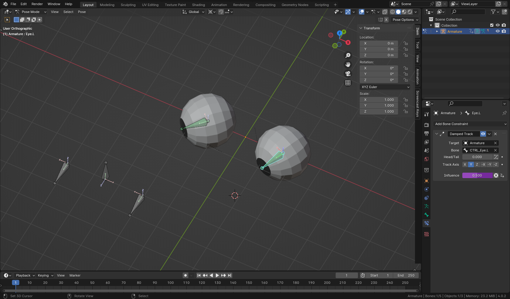
As you can see in this clip; there is a problem here, as I Pose both Pupils simultaneously with the Master Bone. I would like the Pupil that approaches the inner border of the Eye Hole, to be delayed automatically, so it wouldn’t required manual Posing; but because there are 2 Eyes (and they are symmetric: one in relation to the other), I cannot just Rig one Pupil in relation to the other, because eventually, I’ll have to Rig the opposite one in a mirrored way, and then this will return the Rig to original problematic.

I’m not sure how specific is the issue for Eyes Rig. I suspect this can also happen in other Rig scenarios.
In this particular case, though, the Eyes Rig was made using the UV Warp Modifier, so the whole Eye’s Image Texture moves along its UV Map. But more than that, there is no Eyeball Mesh Objects; instead, those are Eye Surface Mesh Objects (which are individually asymmetric in their shape).

I am not totally sure how it develops. Besides relating to a Character Design issue (which is less descriptive to the problem itself), I suspect the problem arises fundamentally from Rigging Eyes containing Eye (Mesh) asymmetry; and it is not necessarily an UV Warp Modifier problem: meaning, if the Eye (Surface) was perfectly symmetric in its shape, or if it were just a basic Sphere Eyeball, and in any of these cases there was an UV Warp Modifier Rig, the problem might not happen (provide the UV Maps which would contain the Eye Image Texture (with the Pupil), were properly centralized with the Pupil in the center regarding the Eye Mesh.

So, currently, I’m looking for different alternatives. Apparently, it’s not trivial.

The main problematic I’m facing, is that the large majority of Blender’s Bone Constraints do not seem to recognize the different in direction; they can recognize orientation spontaneously though.
For example: if we can easily set up a Bone to be Bone-Constraint to move in one orientation, like along on its Local Location X Axis (let’s assume it’s a lateral motion), it is way more complicated to determine, for that Bone, that, if it moves towards the ‘left’ (-X), it should move faster than if it moves towards the ‘right’ (X).

The Automation fix for that Eye Rig of mine is a bit more complicated of course: in my mind, the velocity of the Pupil’s motion must change (diminish), as it approaches the inner borders of the Eye Hole, and of course, this calculation is arbitrary.

I’ve attempted some Driver or Graph Editor, but still not successful.
Apparently, Graph Editor would be the straightforward approach in cases like these?
Is it possible to use Bone Constraint with Graph Editor without any Driver? To make it simpler?
(today, I’ve thought about the possibility of using Action Bone Constraint as Corrective Automation solution).

Any thoughts for alternatives that could solve this problem? Maybe should be thought out of the box, or even use a different Eyes Rig?
Has anyone faced this kind of Eye Rig problem at some point?
Or has an understanding on building these kind of asymmetric, ‘arbitrary/non-regular dynamics’ for Transforms during Automation? Looks like this is not a very much discussed topic?

Thanks for the attention!

What’s the character? At first, I thought it was something else… Just curious

So you lost me at a couple of points

What do you mean by that? That the eyes are basically flat planes, and not a spherical object? Anyway, it’s still a mesh object.

How are you controlling the UV Warp Modifier? Do you have eye bones constrained to follow the eye controller?

Yes, I think this is where you need to be working at. No, you cannot control a constraint without a driver, AFAIK.

So I had an idea about this, created some eyeballs and a simple rig, and gave it a go. It didn’t work. Tried another approach that did work, but I’m not happy with it.

It only works when moving the controller on the -X axis and only affects the left eyeball. The Damped Track constraint’s influence is controlled by how much the main eye rig controller is moved. It works but is a bit wobbly, but that can be fixed via the curves. Right click on the purple influence field and open in the driver’s editor so see how it works.

eye_rig.blend (944.9 KB)

So show me what you’re working with.

Randy

1 Like

Hello!

I’m not an expert in the field, but Pxy-Gnomes helped me a lot by sharing the eye rig for non-sperical eyes tutorial. I believe that the rig Pxy-Gnomes is describing in this post is a newer version of this one 2D Eyes-Track Rig Tutorial. At the end of the second video, it is explained how Pxy-Gnomes connects bones with material using Warp modifier (by filling “object to” with Armature and then “Bone to” with relevant bone for example).

I hope this is relevant

Cheers

1 Like

First, sorry about the delay, and thank you very much for the take.

I just didn’t have enough time to answer properly, including tests.

I also am not sure what happened to my post… I mean, when I’ve posted it I thought it was supposedely to become a new Thread, but it went all wrong and I sort of ‘lost my own post’ until I’ve received the reply :joy_cat: (I might have accidentally post it in the wrong place, even though it seems to make sense to be in this related thread). @Ksusha (so this is actually what happened; but thanks for attempting to clarify).

As soon as I get enough time, I’ll reassess the problem. Sorry for the problems folks.

As for now, I’ve just test enough to suspect that this leads to similar Automation issue that I was having (as soon as the opposite Eye gets Rigged in a Symmetric way, their interdependence sorts of zero out the solution; but the problem is that I’m struggling with the Values in the Graph Editor (there seem to be a Graph’s UI thing, in which is not very clear how to Symmetrize or Mirror things there); so in one sense, I myself cannot test to a complete end your hypothesis because I’m never sure how to make the other Driver+Graph settings for correct Symmetrized Eye (I’ve read something about simply using a Inverted Scale [ something like S > X > -1 ] for the Selected Curce, but I still need to try it out to be sure of what I’m doing).

I still believe, as you said, that Graph Editor is the way around it.
But something I made on this Eyes Rig (maybe UV Warp Modifier makes it harder to solve?) that it is inconsistent and this is also something I want to understand. The Damped Track Bone Constraint I think won’t work (right away at least) with my own UV Warp Modifier Rig, because the latter based on the Eye Bones’ (Local Space) Location Transforms, but then it’s just a question of abstraction (or adaptation); the important would be understanding how to Correctively Automate an existing anomaly.

If I can’t overcome the anomaly, I’ll probably have to rely on a completely different Eyes Rig type that might be safer (that one method that uses “Lattice” for Eyes Rig; it seem to be advantageous because there the Rotation Transform (as in your setup) can be used by Damped Track Bone Constraint, from the center of an actual 3D Eyeball Mesh Geometry for spacial reference which translates 3D (XYZ) to 3D (XYZ), instead of 2D (UV) to 3D (XYZ).

So, it’s about the Locations. Each Eye Control Bone (CTL-Eye.L, CTL-Eye Right.R) needs a specific ‘spacial reference’ (MCH-Eye.L and MCH-Eye.R); sounds excessive or redundant, but this is like the contentional way of Rigging Eyes with UV Warp Modifier. It’s true I haven’t considered yet touching those MCH Eye Bones… because, whichver Location Transforms we do with them (on Pose Mode let’s say), they can be seen as being responsible to do something ‘Inverted’, since the spacial Distance between CTL-Eye.L and its MCH-Eye.L is a relational thing; so in principle it’s easier never Pose the MCH-Eye Bones themselves on their own Local Spaces, but they may still be carried out by… Disconnected Parenting to the Head Bone I think; when the overarching Head Rotates around); but then, there could be a possibility to add special Automation to the MCH-Eye Bones, so to help in solving; I haven’t thought about that previously.

I need a bit more time. Thanks!

I’ve pondered your issue for a bit, and what I keep coming back to is that it seems that there’s an inherent logic paradox here.

You want the right eye to basically restrict it’s range of motion, depending on the rotational value of the left eye… except for when the right eye doesn’t look correct, and in that case you want the right eye to be “set” and for the left eye to be restricted.

One has to be the master, the other the follower. That’s easy, and reversing this is also not to difficult. It’s also easy to set a firm limit on how far the eye can rotate.

BUT - you want the limits to be variable on each eye. The problem is “i want the eye (or something) to automatically give or take control” - and your basic eval for this, would potentially create a paradox if relying solely on the eye rotation value to determine the master. How to decide which is in control?

I don’t know of a way to easily code a driver that puts both eyes in charge of each other 100% of the time, and at the same time puts one eye in charge of the other, based on which visual result is preferred in a particular moment.

2 Likes

I am sort of ‘familiarizing’ with conceived paradox.

If it’s unfeasible spatially speaking, I believe the real cause [of the paradox] is having a Corrective system in which one Eye’s Transform is depending on the opposite Eye’s Transform or similar.

There should be some alternative way to Automate the Curve of each Eye, that does not rely on the opposite Eye’s Transform(s). Technically, if there was something such as an ‘independent Curve’ (for the Location of an individual Eye in space), in which we can just change the velocity of the Eye on certain spacial intervals, that should do…
I believe the Action Bone Constraint can be used to ‘grant’ an Editable Curve (through Key Framed Action) of an individual, independent CTL Eye Bone; so it moves independently of the opposite Eye (and vice-versa if we do that for each CTL Eye Bone), but more than that: this generates the wanted Curve! Otherwise, how we’d get a Curve representing the simple, X/-X Location Transform of a CTL Eye Bone? Relying on a Curve generated from a relational thing (such as Bone Constraint/Driver in some of the original attempts) is extremely more limiting on that case it looks like…, because it should establish the paradox.