Clock - This is looking very good. Landing gear is always a fun one for me…lots of details. Can’t wait to see it textured and in flight.
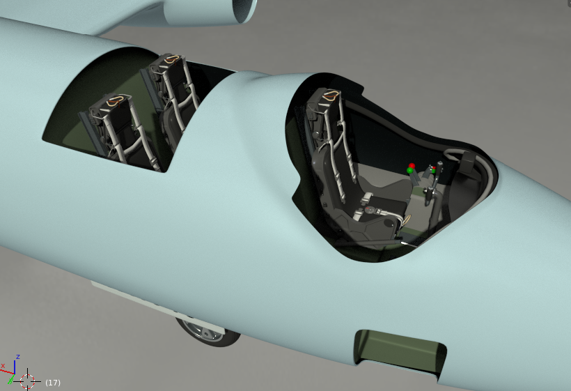
Thank you, yes the landing gear kept me occupied for some time, there is still some detail to go, but I have moved on to my first attempt at three of Martin Baker’s finest:

Still some more detail and the straps to go, but it’s a start, I shall probably do a bit more somewhere else next. I might even start cutting control surfaces. ![]()
Cheers, Clock.
I love old planes, and this one is great 
@Clock - great job on them seats…I like where this is heading. My only issue so far is that the green and red handles/knobs are too flat I don’t seem to see any sort of shine to them. Anywhos…good job
Bit more work around the Stick-Jockey’s seat and the others as well. Plus some “shine” on the throttle controls for Tommy! ![]()

I will probably change the seat belt colours, but it’s high contrast for now so I can see how they look.
Cheers, Clock.
We now have seats in the airframe:
and flaps, after many hours of work (who designed these with all those ******* holes? :spin:):
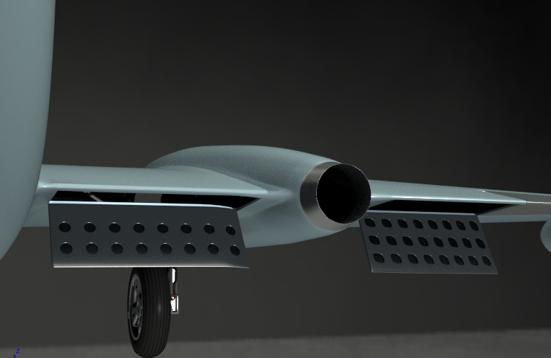
just some hydraulics and hinges to go…
Cheers,Clock.
Clock, the easy and quick way to obtain such lightening holes is the transparency texture! You do not have to model them in the mesh - see in Volume III (Materials and Textures) section 4.9 (“Applying other textures”). The results similar to your flaps you can see (for example) in Figure 4.8.7.
Aaaaaaaaaaaagh - that’s the sound of me tearing out what little hair I have left!
Hadn’t read that part properly…:o
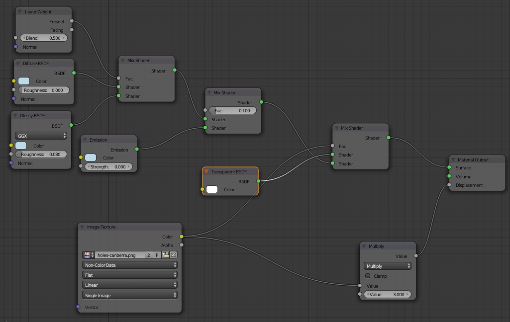
Did you mean something like this:

Only thing is I cannot find the Node Box called “Moderate” in your material picture (pic 3.5.4 et al), so I used a Math - Multiply instead.
The shapes have a Solidify modifier, and a coloured point lamp inside.
I shall use this approach on my aircraft now.
Thanks for the heads-up my friend.
Cheers, Clock.
You are welcome :). Yes, you can also obtain the effect of “sheet metal thickness” along borders of these openings placing the dark areas from the transparency texture on your bump map (just use the same image as a layer in both images: transparency map and bump map). On your picture I can see that the Solidify modifier is also OK (I used the bump map for this purpose).
This is a group node (they are useful: perform the tasks which you often repeat on your node diagrams). In was first introduced a few sections earlier (see Figure 3.2.22).
Thanks, I used the solidify modifier so I got a nice shiny interior surface for the lamp! I go the metal thickness by using the holes image as a bump map also. I will read some more of your book, it’s amazing the things you thought you knew how to do, but Witold knows a better way.
Here’s the material I am playing with on the plane wing, I have hidden a mesh inside the wing, then cut a hole in the wing using the holes image so I can see the hidden mesh - just playing you understand, so I know how this thing works.
Thanks again for your help, Clock.
PS I am going to use this technique for the smaller openings like the Navigator’s window, access hatches, etc. It means that I have got to sort out the UV mapping first for the whole aircraft…
EDIT
Forgot this:

Really coming along Clock. Love the detailed cockpit seating.
Thank you - it was worth all the effort!
@Witold
I have had another play with the technique for cutting holes and noticed two things that are required to make it work:
-
You must have the bounces set to more than 0 for diffuse and glossy shaders or there is a lot of black creeping in.
-
Any other surface that is exactly coincident with the Transparent section also becomes transparent!
Here is an example
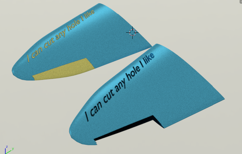
The wing with the yellow aileron and writing has a second copy of the mesh scaled by 0.999, the wing without the yellow bits has exactly the same second mesh, but it is not scaled - weird or what?
To make this test, I made a quick wing profile, UV mapped it onto a plain white image of 2048 x 2048 pixels. I then exported the UV map and used the resultant file as a background image in my Top view, I then drew on two planes for the ailerons and added some text, both of which had a black diffuse shader. I then set the camera to look down the Z axis and set it as to Orthographic mode (Not Perspective), I then set its size to 2048 x 2048 and lined it up with the background image. I then set a White Background shader and rendered the view with just the black shapes and text displayed. I then used this render as my “Transparent” & “Bump” maps to produce the cutouts and the edge thickness. I found this method much easier than using Inkscape. What do you think to that?
Cheers Clock.
PS Does anyone have any photos, aerial shots, maps or Khormaksar airfield in Aden, now The Yemen? I’d be really grateful if I can get one.
Just throw “Khomaksar airfield” into a search engine and you’ll get aerial photos on the first page of image results.
Great modelling. Keep it up.
Thanks - the problem is I want to reproduce the airfield as it was in 1956 - this seems a bit harder to track down.
Cheers, Clock.
Yes, really strange! I will check it on a simple box model - maybe the “transparent texels” overcome the opaqe texels because they have the same Z coordinates in the camera coordinate system? (The renderer determines these Z coordinates for each pixel of the rendered image - this is so-called “Z buffer”).
Every method is good, as long as you found it easy and it produces proper results :)!
[SUB]I use Inkscape because it produces scalable drawings and has a rich set of 2D drawing tools. The shapes from the transparency map are just a part (the simplest part!) of the complex picture used for creating bump maps and basic reflectivity map. (For example: usually you have to draw rivet seams along these openings. They should appear on the bump and ref maps). I think that you can create rivets in Blender in the way you described above, but I just did not dare to create tens of thousand dots in this way. It is just a kind personal preferences: for me it is the same, to draw a square and a text in Inkscape or in Blender. I also observed that usually the progress of my work over a model is not like a “waterfall”, but resembles a spiral. I often have to modify some of the finished parts, because I have found a better reference photos and it occurs that I previously shaped them in a wrong way. It also forces further changes in the textures. For such a workflow I prefer to keep the source drawings of the skin technical details in Inkscape. (I can just tweak some of the rivet lines or panel seams, instead of drawing them anew). It would be also possible in your solution in Blender, but I think that a little bit more complex (you would have to modify the 3D objects just to modify their “shadows” on the 2D plane).[/SUB]
Thanks for that - I have now set up a separate blend file to create the basic lines and holes images as I described previously - then I take them into Inkscape to add the rivet lines and other “fine” detail and shading, This gives me a better workflow to draw really accurately before I start the “tweaking”. So a combination of both seems to work well as a workflow and does not clog up the main project with all the image related work. I have also created a camouflage image from shapes in blender, then used this to produce a surface colour, including the roundels. I also noticed some ghosting of the holes on the main wing surface, so introduced a Math - Multiply to the feed from the “holes” image to the Transparent/Colour shade mixer with a value of 1.1 to get rid of them - pure guesswork here, but it worked.
Here is a test image from this new process, no rivet lines just yet:
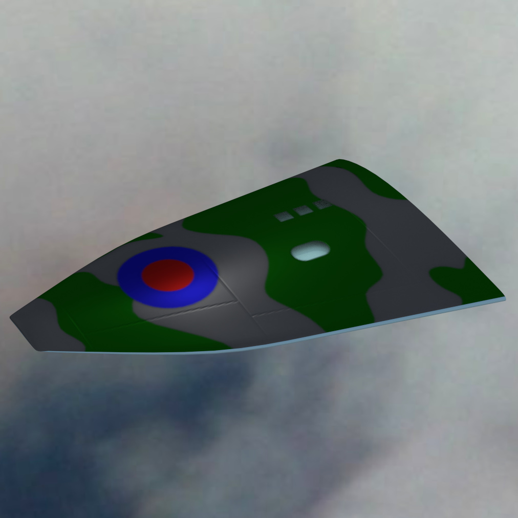
I have cut some holes in the wing, but not put anything inside them yet, so the light coloured underside shows through the holes. I coloured the “colour” image camo for one bit and light blue for the other, then UV mapped the top and bottom of the wing onto the separate areas. The camo areas where just a flat set of Quads with a sub-division modifier to smooth the shapes, on a grey background.
Cheers, Clock.
PS. I am now happy with the basic process and will go onto look again at the Canberra, I am going to remove all the cut outs and about 3 million edge loops in the process, and try again with the “Witold Holes” technique and see how I get on. I will try this on the control surfaces, windows, hatches , u/c doors et al and see if it works, on a copy project of course! I will report back later…
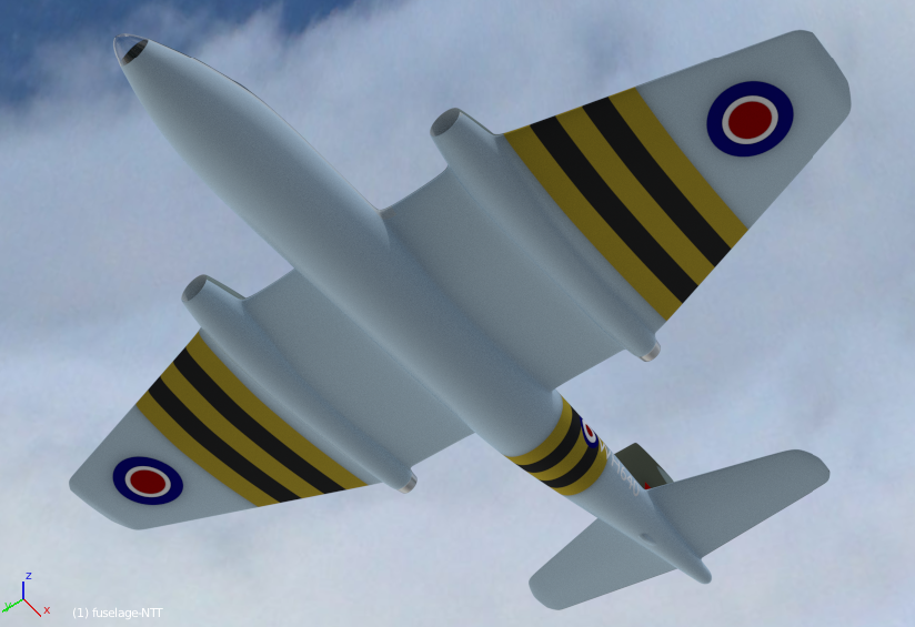
First attempt at a material render, long way to go still, but it’s a start. I am not happy with the text just yet, but everything else seems to be working out. I will need to tweak the render material image in Gimp, and then think about bump maps and holes.

Cheers, Clock.
She’s looking like its time for her first flight - nice job
Hey Clock, I found this plugin very helpful https://sites.google.com/site/pointatstuffweb/external-paint-autorefresh I reckon it could help with the text