SBD Dauntless (US Navy dive bomber)

You are welcome :).

Yes, they have been as the default mode of the Subsurf modifier since I remember. In fact, this very functionality was the key reason of choosing Blender as the program for aircraft modeling. I did it in 2006. [SUB](see here for more details about other alternatives)[/SUB]

In the previous post I have formed the general shape of the Dauntless wing. Now I will work on its trailing edge, separating the aileron and flaps. They were attached to the internal wing reinforcements. These reinforcements were distributed in parallel to the trailing edge:

In the first step I will split the wing mesh along this line. However, before I do this, let me mention a certain geometrical effect which can be surprising for many modelers. (Frankly speaking: it was also surprising for me — I knew that such an effect exists, but I thought that its results can be neglected for this wing area).

When you place on the wing a plane shaped like the “cutting line” shown on the picture above (see below, left), you will discover that the resulting intersection edge on the wing surface forms a curved contour (see below, right):

The curve on the wing tip is not a surprise, but why the intersection of the flat plane and the wing trapeze (i.e. the line between point 1 and 2) is also curved? The answer is: because this wing is like a section of an elliptic cone. The only straight line on the cone surface connects its base and apex. Any other direction (like our cutting plane) produces a curve. When the curvature of the wing airfoil on this area is low, the deviation from the straight line can be neglected. However, in this wing it produces a 0.23” deviation at the aileron root rib. You had to adapt contours of the spars and stringers used there.

Obtaining such a gently curved shape on a relatively long element is difficult from the technological point of view (i.e. costly). It can be applied if the high performance is on the stake (as in the Spitfire case). However, even the Spitfire designers had to make a compromise with the workshop and made the bottom of their wing flat. (In this way they provided a technological base).

What could do a pragmatic Northrop (then Douglas) designer in such a case? I have no direct photographic proof, but it seems that they approximated this shape with two straight segments. They are split at the aileron root section:

In the next post I will show you that in this wing each of these two segments was made in a different way. The flaps were attached to a reinforced vertical wall (a kind of a partial spar), while in the front of the aileron there was a lighter structure matching the shape of the aileron leading edge.

After these deliberations we can cut off the trailing edge from the wing:

(I did it in two steps. In the first step I created a new edge along the intended split line, using the Knife tool. In the next step I separated the rear part of this mesh into a new object).

We will deal with the red elements in the next post. In this post let’s recreate wing details along the flaps and aileron bay:

The ultimate edges of aileron bay are located a little bit further than the “reinforcement line”. I extruded them from the original mesh.

When a part of the original control mesh is removed, the shape of the resulting object can have small deviations from the original shape of the complete wing. Thus before I separated the trailing edge I copied the complete wing into an auxiliary, “reference” object. Now I am using it to ensure that all these newly extruded vertices lie on the appropriate height:

On the picture above you can see solid red areas around the modified vertex. This is the result of the approximation of the curve section (the flap hinges have to be straight lines).

To determine exact shape of the aileron bay edges I placed an auxiliary “stick” along the aileron axis, as well as some circles around it. The radii of these circles match the shape of the aileron leading edge (+ the width of the eventual gap — see picture below, bottom left). Then I set the view perpendicularly to this aileron axis object, and used auxiliary circles to determine the shape of the aileron bay edges:

Finally I closed the aileron bay with a curved wall that matches the shape of aileron leading edge:

In this source *.blend file you can check all details of the mesh presented in this post. The next post will report further progress on the wing trailing edge details (I will form and fit the aileron).

Nice work. These tips are going to be valuable for things other than planes too.

@Gumboots, thank you! I am glad that you have found it interesting!

In the previous post I have modeled the aileron bay in the SBD Dauntless wing. However, it was one of the cases when I followed my intuition and the mathematical precision of the computer models instead checking how this detail looks in the real airplane. So let’s do it now. I have reviewed many photos. The figure below shows the one which is the most useful (made by my friend in 2014 in one of the air museums):

We can see here that the flaps are attached (via a very long hinge) to a reinforced structure which resembles a spar. It ends at the first aileron hinge. On the other hand, the aileron is mounted on three “point” hinges which protrude from the ribs. Thus the curved sheet metal that closes the aileron bay has much lighter structure, because it is merely a cover. It is riveted to the ribs and other wing skin panels. The “sharp corner” at the upper edge of the aileron bay is obtained by a fragment of the upper wing skin that overlaps (by about half of inch) the bent, rounded edge of the internal wall.

I recreated in my mesh the auxiliary spar along the flaps and the fragment of the wing skin that overlaps the upper edge of the aileron bay:

I will model the bent upper edge of the internal wall later, during the detailing phase. The lightening holes in the spar will not be modeled. For such less important openings I will use transparency textures.

At the beginning of the previous post I cut off the wing trailing edge. Now I split it into two objects: the aileron and the flaps. Then I started to work on adapting the aileron mesh. First I simplified its topology: I slid its upper longitudinal edge forward, where the curved leading edge begins (Figure a), below). I do not need its bottom counterpart, so it will disappear. In the effect the aileron cross section resembles a triangle, as in the real airplane. (Such simplifications of the theoretical trailing edge geometry were common in this aircraft generation).

To form the curved shape of the aileron leading edge I extruded vertically from its bottom edge two face rows (Figure b), above). Then I closed the remaining gap with another row of faces.

After small adjustments of their vertices at the wing tip I obtained the rounded shape of the aileron leading edge:

Then I did some further adjustments, checking if the gap between the aileron and the wing is wide enough (0.2”) for the whole aileron rotation range (from -10⁰ to +17⁰). You can see the result in the figure below:

However, comparing this result with the photos, I discovered that I fitted it too tightly! What’s more, I also noticed differences in the shapes of the aileron tip and its bay between various restored aircraft:

The outer wing panels were the same in all the SBD versions (at least their external details — see this post) — so I cannot explain these differences as the differences between various aircraft versions. Well, it seems that one of these restored aircraft was modified afterward. But which one?

Restored aircrafts are great resource of information for all modelers. However, some of them contain various modifications. Most of such differences you can find in the airplanes restored before 1990. Since that time the average level of restorations has significantly improved.

To determine which case is wrong, you have to look at the archival photos:

In the picture of a factory-fresh SBD-1 you can see that the tip of the aileron was curved. Nevertheless, I had to widen the gap between the aileron and the wing tip, reproducing the case I can see on the archival photo:

In this source *.blend file you can check all details of the model presented in this post. In the next post I will recreate the flaps.

Interesting. I wonder why they bothered curving that leading edge. It’s more complicated to make, and I can’t think of any advantage.

Well, not everything in the aircraft design is based on calculations. Especially in the late 1930s, there were many elements which shape was based on practical experience and/or designer intuition. There were even some fancy elements added just to improve airplane appearance. However, in this case the designers tried hard to improve aileron efficiency near the stall. This shape can be the result of one of their trials (ultimately they succeeded by adding fixed slots at wing tips).

I am leaving on vacation (away from the computer for two weeks). I will describe further progress of my work on the SBD Daunless on August 29th.

Perforated split wing flaps were the hallmark of the SBD Dauntless. Their inner side was reinforced by the “grid” made of stringers and ribs. Because these flaps were often wide open — during landing or in dives — I have to recreate their internal structure. In this and the next post I will describe how I did it.

All the SBD flaps had fixed chord (they were made from perforated sheet metal of rhomboidal shape). After studying many photos I assume that all their ribs have the same size and shape — also the parts attached to the trapezoidal, outer wing section. It seems that Douglas factories built all five flaps of the SBD in the same way, using unified components. The flaps for the external wing panels had to be twisted a little during riveting — most probably on appropriate mounting pads. The trailing edge of the upper flap is the trailing edge of the whole wing. It was a thin wedge, profiled from a sheet metal and riveted to the flap skin:

(Similar wedge is riveted to the upper skin of the center wing — see the picture above). The chordwise contour of these flaps looks flat on the photos. In fact there is only a small difference (less than 0.2 inches) between the theoretical contours of the wing airfoil and a straight line on the area around the trailing edge. I think that for the designers such a technological simplification was not a big deal — they had already made a more serious modification by perforating the flaps.

I started building the SBD flaps by creating their upper and lower planes. (I created them by simplification of the mesh fragment that I previously cut off from the wing). I used the Solidify modifier to give them thickness of a sheet metal. (I used this modifier for all parts which I will create in this post). Then I added the wedge (another object) along their trailing edge:

I started this wedge as a single contour, which I extruded along the whole span of the flap. Because of the trapezoidal shape of this wing, I had to twist a little the outer end of this wedge, fitting it better to the upper flap. Then I shortened the trailing edge of the bottom flap, fitting it into the wedge when it is closed.

When it was done, I added the main “spar” of the flap (in fact it was a U-shaped stringer). I did it in the same way as I created the trailing edge: shaping the profile, then extruding it lengthwise:

Once extruded, I had to rotate this object and twist its end, lying its outer edges on the inner surface of the flap skin. To facilitate this process I assigned this object a contrast, red color.

While fitting this spar, I discovered that the twisted, four-vertex face of the flap skin has small elevation along its diagonal (as in picture above). It is not something “real” — just an effect of the internal decomposition of all quads into triangles made by Blender.

To eliminate this artificial effect I had to divide this sigle, large face into several smaller pieces:

It minimized the influence of Blender internal “triangulation” and allowed me to properly fit the stringer to the flap. As you can see in the picture above, the end profile of this spar is twisted, following the twist of the flap skin.

After the first stringer I created in a similar way two other reinforcements on the flap edges:

As you can see, I used two clones of the rib contour. (I needed them to determine slopes of the front and rear reinforcements in the side view — as in picture above).

When the flap lengthwise reinforcements are in place, I can add the ribs:

All the internal ribs are clones of a single mesh. The external ribs have the same contour, but each of them has its own mesh (because they do not have the cutout for the central spar, as the internal ribs). These flap ribs have quite complex shape, but I managed to keep their mesh quite simple. It was possible, because a part of this complexity (the sheet metal thickness, rounded edges) is created by the Solidify and Bevel modifiers.

When the ribs were in place, I added the last stringer. It was a “L”-shaped beam:

Modeling internal structures of the flap forced me to carefully measure anew all of its details, especially the width and location of its spars. In the effect you can see that my wing drawings are not as precise as you could expect:

In this source *.blend file you can check all details of the model presented in this post. In the next post I will continue my work — this time on the upper flap.

Found this thread, and i’ll save it. It’s a superb reference both on the Dauntless and Blender modelling.
super stuff ! Thank you.

Welcome! It is a great honor for me that such an experienced artists as you found this thread interesting! Thank you, Galgot! I will do my best :).

Inspiring to see your incredible level of detail in preparation! Can’t wait to see where this goes!

Man, it’s like you’re modeling this to fool the FBI into thinking it’s a real plane. You’ve put a monstrous amount of effort into matching every little detail, and I respect your precision.

@paulchambers3D: thank you!

Well, let’s not exaggerate: at this moment it is relatively simple structure: just crossed some stringers and ribs. I will have to do much more in the future, during the detailing phase… You will see :).

In this post I will create internal structure of the upper split flap. Structures of both flaps are similar, thus I started this job by copying stringers from the bottom flap, finished in the previous post:

Every copied stringer is a duplicate of its counterpart from the bottom flap (I just used the negative scale: -1). I had to rotate these objects, placing them on the internal side of the upper flap skin. I copied the internal ribs in the same way (see picture below). (All of them are clones, which use the same mesh):

As you can see in the side view (see in the picture above, upper left), there is just a small vertical distance between the last ribs of the upper and lower flap (i.e. at the aileron). This is the thinnest place of this structure.

At the trailing edge of the upper flap there is the profiled wedge (I described it in the previous post). The upper flap is little bit wider (it has longer chord length than the bottom flap). Because of this the ribs of the unified size used in these flaps are too short to reach the closing wedge (see picture above).

We can observe this effect on the photos. To make these ribs longer, designers added at their ends small “U”-shaped profiles (see picture below):

I recreated these elements in my model (see in the picture above, right).

The upper flap has a cutout in its inner edge. Thus there is “one and half” of the external rib here:

I recreated this structure in my model and modified the mesh of the upper skin:

These flaps were attached to the wing by two long hinges. I recreated them as two very long cylinders and placed between the flaps and the wing:

Now, when I rotate the hinge along its local Z axis, the whole flap rotates, like in the real aircraft:

This is a preparation for the future animation of this movement (during the detailing phase).

In this and the previous post I built the split flaps and their basic skeleton. I recreated these ribs and stringers because they are visible when the flaps are extended. The additional benefit of this work was the verification of my reference drawings. (Now I know that I have to shift a little the perforation and rivet seams on both flaps. I will do it when I prepare their textures). However, on this stage it is too early to finish all remaining details of these flaps. It still may happen that I will discover something which will force me to modify the geometry of this wing and its flaps. Thus in the picture below I marked what I prefer to postpone until the detailing phase:

As you can see in this picture, I will create the openings in the flap skin later. At this moment I am going to recreate them using the same technique as for the lightening holes: textures (the bump map and transparency map). However, if this idea fails, I will model these openings in the flap skin mesh. (This method requires much more time than the textures).

In addition to these openings I will also recreate all the minor details of the flap structure. For example — I will split the “L”-shaped auxiliary stringer between the ribs. I have also to split the flap forward reinforcements into separate segments.

The complex system of the flap actuators will be also a challenge for the detailing phase (however, I already analyzed how it works).

In this source *.blend file you can check all details of the model presented in this post. In the next post I will create the fixed slats and finish this outer wing panel for this “general modeling” stage of work. Of course, I will work on it again later, during texturing and detailing.

In the next post I will add fixed slats, completing this outer wing section.

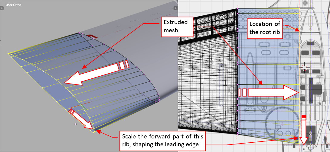
In one of the previous posts I showed the details of the aileron bay. Now I separated the corresponding wing mesh fragment into a new object. I bent its upper edge like it was depicted on the photo:

On some photos I could see that this wall was built of two pieces of sheet metal. Their seam was located below the aileron pushrod.

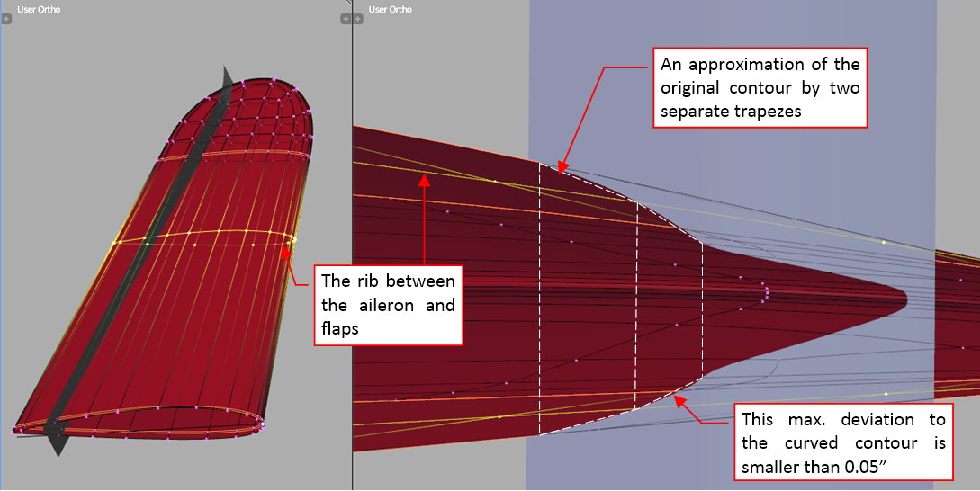
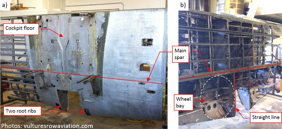
The reason for such split became obvious after the comment I received from one of the readers (thank you, Brian!). It happened that a few weeks ago he visited the Yanks Air Museum in Chino, and had an occasion to examine wings of their SBD-4. He reported that while the bottom edge of the aileron bay is a straight line, the upper edge has a break at the pushrod. The difference from the straight line at this point is about 0.1-0.2 inches. Checking this tip, I examined photos of this particular SBD-4, then I verified photos of the other SBD version:

This nuance of the aileron edge is hardly visible in a perspective view. It explains why I missed it studying the photos!

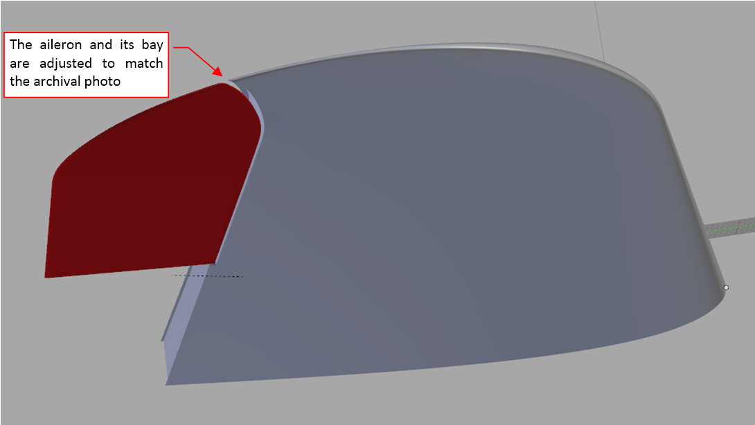
Finally I recreated this detail in my model:

(Doing it, I had to modify shapes of three objects: the wing, the rear wall of the aileron bay, and the aileron).

I could not resist the temptation to recreate the rounded corner of the wing skin at the aileron root:

Frankly speaking, I should model such a thing during the detailing phase. I allowed myself to use some n-gons (faces that have more than 4 vertices) here, because this surface is flat so these n-gons will not deform the smoothed result.
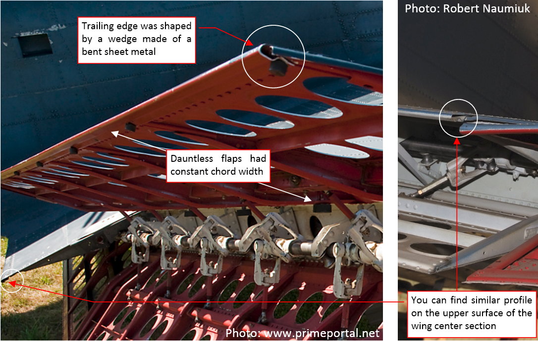
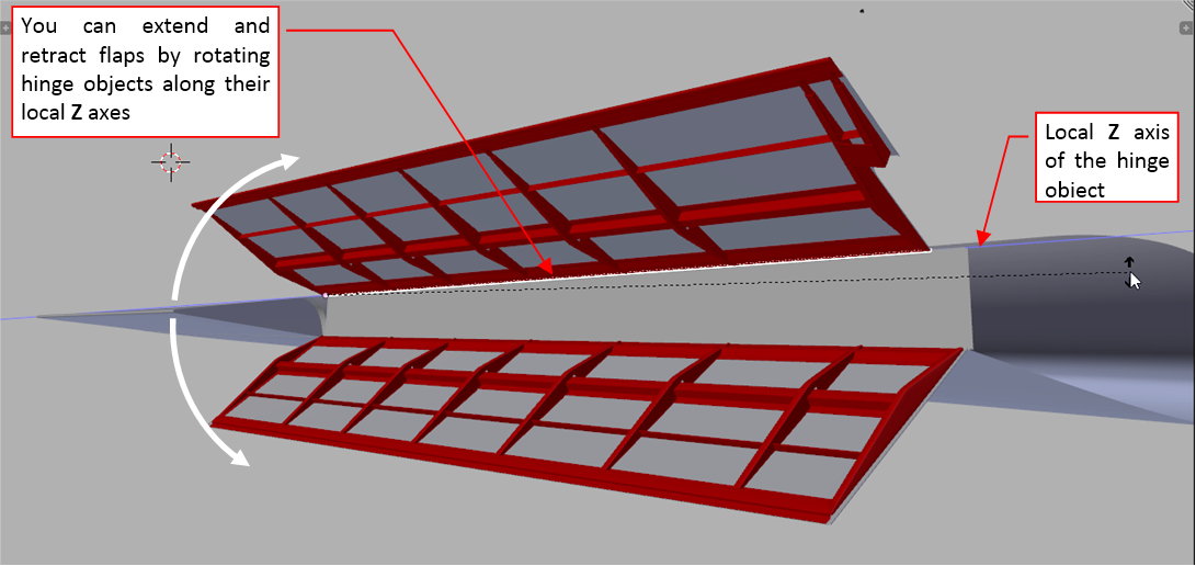
However, looking on the photo above I noticed that the aileron bay edge seems to lie on the same line as one of the rivet seams on the flap. (The seam that runs along the rear edge of the hinge reinforcements). So it was on the reference drawing. However, do you remember that I had to modify these flap reinforcements, shifting them forward (in this post)? So now I know that this rivet seam is in another place on this flap, different from the place where you can see it on my drawing. Now I have to update accordingly the location of the aileron edge!

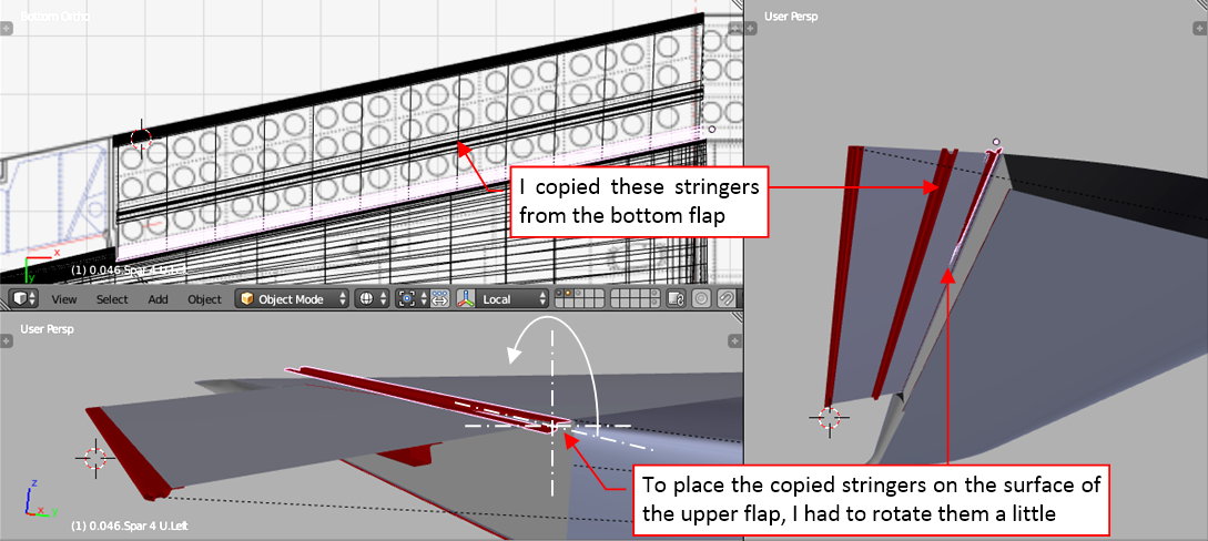
To preserve its vertical shape, I did it by two rotations: first I rotated it along Z axis:

Then I had to make a small rotation along Y axis (along the same pivot point), elevating these faces back onto the wing surface.

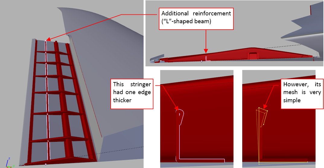
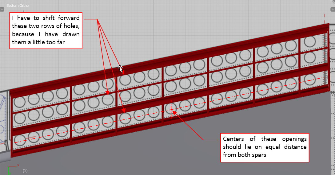
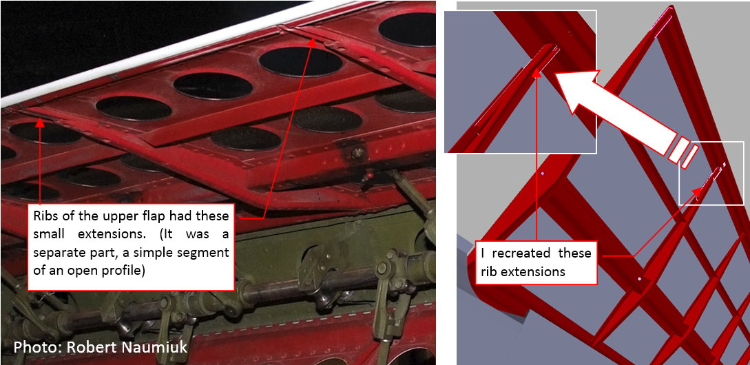
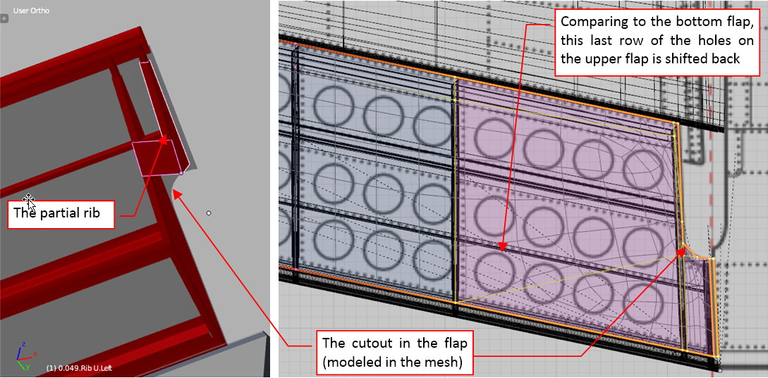
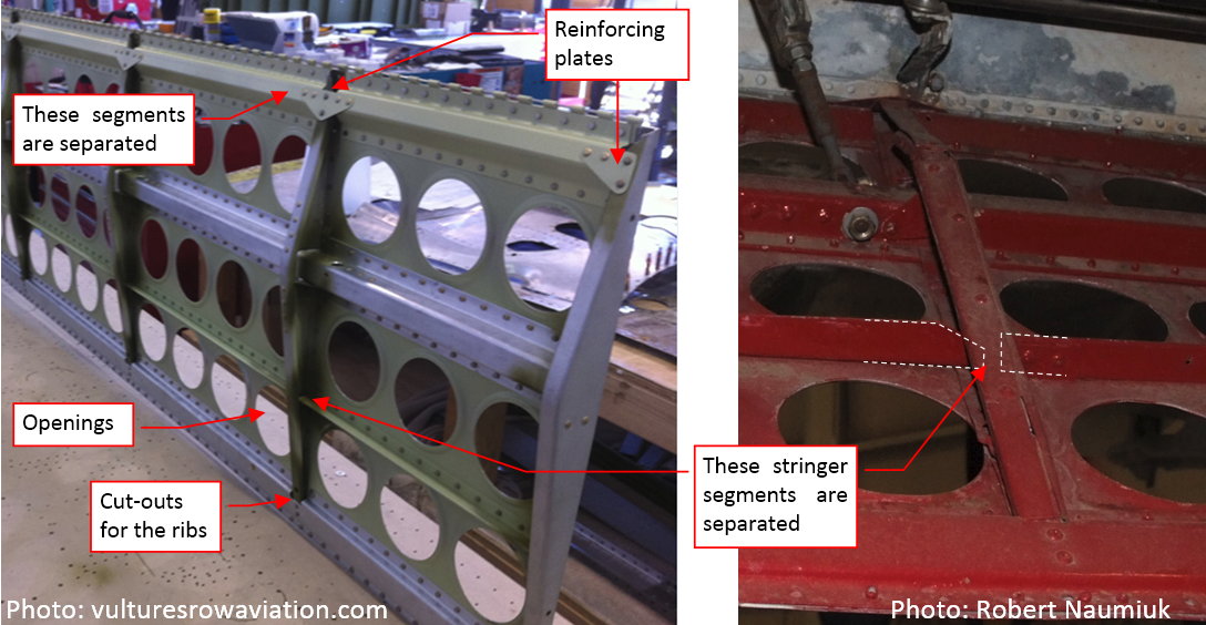
The updated layout of the flap ribs and struts means that I will have to move forward not only the rivet seams, but also the rows of the circular openings placed on the flaps (I mentioned it in one of the previous posts). What’s interesting, the auxiliary “L”-shaped stringers on the upper and lower flap have different chordwise locations. In the result, the last row of the holes in the upper flap does not match its counterpart on the bottom flap (see picture above).

The last detail I will recreate during this stage of work is the fixed slat. It requires six openings in the wing skin: three on the upper surface and three on the bottom surface. I did not modify the wing mesh for this purpose, because additional edges around these openings would seriously complicate its topology. I decided to create them in another way: it may happen that ultimately I will make these holes using transparency textures, but for now I will do it using the Boolean modifier. First I prepared an auxiliary object — the “cutting tool”

I set the wing as its parent, and placed on a hidden layer. Then I used a Boolean modifier to dynamically cut out these openings in the wing:

Note that I placed the Boolean modifier after the Subdivision Surface modifier, to cut these holes in the resulting, smooth wing surface. As an additional bonus, this modifier also creates their internal walls (they come from the auxiliary object).

Although the “rib” walls obtained in this way are OK, I decided to create the front and rear walls of this slat as a separate object. Why? Because it is easier to modify its shape when it is not split into three “boxes”, as the “cutting tool” object is:

I will join all these internal faces of the slats during the detailing phase. Currently I am leaving them in the current state, just in case I will have to modify the wingtip geometry.

This was the last element of the outer wing panel I wanted to create during the “general modeling” phase. I will recreate all of remaining parts (landing light, approaching light, Pitot tube, aileron axis arms, etc.) later, during the detailing phase.

In this source *.blend file you can check all details of the wing presented in this post.

Note: When you open this file, the Boolean modifier may not work properly. The slats will appear when you enter the Edit mode of the wing object, then switch back to the Object mode (i.e. select the wing panel and press twice the [Tab] key). It seems to be a minor bug in Blender: it happens when the object having the Boolean modifier is simultaneously the parent of the “cutting tool”. (More on various modeling issues you can find in Vol. II and Vol. IV of the “Virtual Airplane” guide).

In the next post I will start working on the center wing. It will be occasion to find another parent for the “cutting tool” object, resolving the issue of disappearing slats.

@Witold, one thing’s for sure…many generations will talk about a great man that used to rock airplane modelling.

All I have to say is OMG and thanks for sharing. I’m curious to know how many verts/polys so far?

On the first glance the SBD center wing section seems to be a simple rectangular (i.e. constant chord) wing, with modified leading edge:

However, the landing gear openings visible on the photo can be difficult to recreate in a mesh smoothed by the subdivision surface modifier.

Additional photos from one of the SBD restorations made by Vulture Aviation in 2012-2013 reveal that the fuselage was mounted on the top of the wing (see the a) picture below):

A part of the upper wing surface was simultaneously the cockpit floor. Note the rectangular cutout in the middle of the leading edge. The SBD had a small window on the bottom of the fuselage, in the space between the two root ribs.

On the photo of the bottom of this wing (as in the b) picture, above) you can see that these root ribs had a modified airfoil shape: it bottom contour has a straight edge from the leading edge to the main spar.

I started to form the center wing section by preparing the single curve of its external rib. (I copied it from the root rib of the wing reference object, which I used during modeling of the outer wing panel):

I think that creation of these large landing gear bays (as the first picture in this post) will require a lot of modification in the wing mesh. Thus I decided to separate the mesh fragment that contains these openings (from the leading edge to the main spar) into a separate object. (It is always easier to modify topology of such a medium-size mesh part, than the whole wing). To ensure a smooth, invisible seam between this forward and the rear part of the wing, I had to accordingly prepare the control polygon of the initial airfoil. I added an additional point on each side of the vertices located above and below the spar line:

What’s important, such three points have to be collinear. The resulting subdivision surface “touches” the middle point of such a fragment of the control polygon, and it is tangent in this point to these two adjacent control polygon segments. (This is just one of the mathematical properties of the Catmull-Clark subdivision surfaces, which are implemented in Blender).

However, these four new control points altered the shape of the airfoil curve. Now I have to fit this shape to the original NACA-2415 airfoil of the outer wing panel:

Fortunately, the Catmull-Clark curves/surfaces have another property similar to the NURBS: so-called local change. Their formula ensures that influence of a single control point does not exceeds two subsequent segments of the control polygon (two segments in both directions — see picture above, right). It is easier to focus on the modified mesh fragment, when you know this rule.

Once the initial rib shape fits the outer panel, I can extrude it forming the center wing section:

To shape the leading edge I had to stretch a little bit the forward part of this mesh. As you can see (in the picture above), I placed this new edge loop in the place of the wing root rib.

However, comparing the resulting object with the photos I discovered that the leading edge of the center wing section should have constant radius (at least approximately):

In this way I have found another error in my reference drawing: the wrong shape of the root airfoil:

The tangent direction at the wing spar differs from the direction estimated on the drawing, thus the bottom, straight segment of the root airfoil has a slightly different slope. The leading edge is much thicker than I draw on these plans.

Adapting the well-known von Moltke’s sentence: “no plan survives contact with the enemy” to this situation, we can say that “no scale plans survive contact with their 3D model”. :slight_smile:

I created a first approximation of the main wheel (it lacks the details) to check if it fits into the space between the leading edge and the main spar:

When I was sure that the shape of the wing is OK, I separated the forward part of this mesh (by splitting it along the main spar). As you can see (in picture above, right) these two parts join in a seamless way. It was quite simple to prepare such an effect in the initial curve by adding additional control points (as I described in the beginning of this post). It would be much more difficult to introduce similar modifications into the extruded mesh.

If you want to learn more about properties of the Catmull-Clark subdivision surfaces, as well as the details of the modeling workflow, see Vol. II of the “Virtual Airplane” guide.

In this source *.blend file you can check all details of the wing presented in this post.

In the next post I will create the opening for the landing gear.

In this post I will cut out the opening of the landing gear bay in the wing. In the SBD Dauntless its shape consists a rectangle and a circle:

However, when you look closer, you will notice that the contour of the main wheel bay is not perfectly circular. There is a small deformation of its shape on the leading edge (see picture above). I think that it looks in this way because of the technological reasons. Another feature of this opening is the fragment “cut out” in the bottom part of the fuselage, below the wing. (We will make it when we will form the fuselage).

I started by applying all the information that was confirmed by the general arrangement drawing and various technical descriptions: the main wheel used 30”x7” tire. Its center was placed 18.5” from the firewall (measured along the global Y axis)

The X coordinate of the wheel center can be determined by the location of the root rib (10”) + small gap + tire radius (30”/2) ≈ 26”.

Then I tried to put around the main wheel a test contour of the opening in the wing:

Initially I thought that I will recreate this opening by embedding a subdivided octagonal hole in the wing mesh, as I did in my P-40 model (see Vol. II of the “Virtual Airplane” guide).

A subdivision curve based on an octagon produces nearly perfect circle. It does not matter if vertices of this octagon lie on different depths — as long as they form an octagon in the vertical view, the curve based on such a control polygon looks like a circle in the vertical view. (The mathematicians call this property “projective invariance”, it also applies to the NURBS curves). When you know it, it is much easier to model various mechanical shapes.

However, when I created an appropriate octagon around the wheel, I discovered that one of its vertices lies outside the wing mesh (see figure a), above). You cannot compose such a contour into the wing. Therefore I decided to create this opening using another Boolean modifier, as I did in the case of the fixed slats (described in one of the previous posts). I prepared the basic contour of the “cutting tool” — a smooth circle based on a 16-vertex polygon (as in figure b), above).

The fragment of the main wheel opening that “touches” the wing leading edge seems to be flatten a little (see the first picture in this post). To obtain such an effect I rotated the “cutting tool” object (the ring) by a few degrees so its Y axis was perpendicular to the leading edge. Then I shifted a little the single edge of this ring along the Y axis, fitting it into the wing:

By small movement of these two vertices I was able to precisely recreate the shape of this opening visible on the photos:

If I do not want to get the inner part of the “cutting ring” inside the resulting opening, I have to assign to this wing mesh a sheet metal thickness (using the Solidify modifier – as in picture below):

Because the forward and rear part of the wing are separated, I can use this Solidify modifier only in the front part. In this way I do not increase the polygon count of this model with unnecessary faces.

As you can see in the picture above, I also created a second “cutting object” — a box. I will use it to recreate the rectangular opening around the landing gear leg. Both of these tool objects are located on a single layer (9) which will be hidden during rendering. Their parent is the rear part of the center wing section (to avoid dependency conflict with the front part of the wing).

Finally I assigned both of these “cutting” objects to the Boolean (Difference) modifiers of the wing skin (The same method as used for the fixed slats). You can see the result in picture below:

It would be quite difficult to recreate such an opening by altering the control mesh of the wing skin. It also would make its shape more complex, and difficult to unwrap in the UV space (for the textures).

The openings created by Boolean modifiers have another advantage: it is very easy to modify their contours. I had to do this just after I created these holes. I discovered that I made minor error in the reference drawing: the landing gear leg opening should lie a little bit back. (Its centerline should pass through the landing gear wheel center

All what I had to do was to shift back the auxiliary box object, which creates this opening. So easy!

On the other hand, I observed small shadows caused by triangular faces created by the Boolean modifiers along edges of this opening. It was impossible to remove them in the typical way — using the Auto Smooth option or the Edge Split modifier. The only solution was to increase (from 2 to 4) the level of the Subdivision Surface modifier assigned to the wing surface object. It increased 16 times the number of resulting smooth faces created from this mesh. Fortunately, I split the wing into two parts, so I could set keep such a dense mesh only around the area where it is needed.

In this source *.blend file you can check all details of the wing presented in this post.

In the next post I will create main spars and ribs, visible inside this opening.

Inside the Dauntless landing gear bay (which I cut out in the previous post) you can see fragment of the wing internal structure. Because I plan to create this model with retractable landing gear, I have to recreate these details. During this “general modeling” phase I will create here just the few key ribs and spars. I will show it in this post. The remaining details have to wait for the detailing phase.

Examining the photos I identified two auxiliary spars and three ribs as the key elements of this structure:

The spar is relatively simple to recreate. Initially I created a rectangle. Then I split it into six faces. Then I removed one of these faces, creating the space for the wheel bay:

Then I added flanges, rounded corners, and the sheet metal thickness, to give this spar a more realistic look, as you can see in picture “a”, below:

However, when you examine this object, you will discover that the mesh of this spar is very simple (as you can see in picture “b”, above). I obtained all these effects using a Solidify and two Bevel modifiers. It even did not require any special smoothing (I did not use the Subdivision Surface modifier here).

In the same way I created the second spar:

While working on these spars I also decided to recreate the wing skin that covered the gap between the main spar and Spar 1:

It would be possible to shape such a hole by altering the wing mesh. However, if I already used the Boolean modifier in this object to cut the opening for the landing gear, it was much simpler to extend it for this purpose. Thus I extruded the whole leading edge section, up to the centerline. Then I cut out a part of this newly created surface using the modified “cutting tool” object that I used to form the landing gear bay (as you can see in the picture above).

The mesh of the wing skin already contains a “rib” edge loop in place of the root rib (see picture “a”, below). Thus it was easy to duplicate this edge into a new object, and extrude it by an inch into a flange. I offset this flange by a metal sheet thickness, placing it below the wing skin. (I did it by applying a temporary Solidify modifier — in Blender it produces better results than the Offset command). Finally I created faces between the vertices of the upper and lower rib edges (as in picture “b”, below):

As in the spar, the rib object uses a Solidify modifier to recreate the sheet metal thickness and a Bevel modifier to round flange edge. It also uses Subdivision Surface modifier to fit it tightly into the wing.

A new rib that fits a trapezoidal wing segment requires somewhat more work. To create it, I prepared auxiliary “cutting tool”: two parallel planes (as in picture “a”, below):

I used this helpful Intersection Blender add on (I created it for similar purposes) to find the intersection of these two planes and the wing mesh. I separated the result of this operation — two edge loops (see picture “b”, above) into new object. Then I continued as in the case of the previous rib: created the flange (see picture “a”, below) and offset it from the wing skin. In this case I had to modify the bottom part of the rib, creating space for the wheel bay. Finally I created the vertical walls (see picture “b”, below):

In similar way I created another rib. You can see the result in the picture below:

At this moment I am not recreating in this structure the lightening holes — I will obtain this effect using bump and transparency textures.

I mentioned the “textured holes” many times in the previous posts. However, I will apply it much later, during the texturing phase. Thus, if you want to find more about this particular method, you can find its detailed description in Vol III of the “Virtual Aircraft” guide. (It is an introduction to materials and textures).

In this source *.blend file you can check all details of the wing presented in this post.

In the next post I will create the remaining elements of the wing.

Good work Witold!

It looks like fairly interesting modelling and it is starting to create ideas about how and why the plane was built that way.