That’s pretty impressive clockmender!
He’s got a couple of glaring errors in his tut. He’s got the aelerons and landing flaps moving in unison with the elevators when the plane pitches up or down. Only the elevator should move. And the landing flaps should only rotate downward, not upward.
I did the video below using drivers to move the control surfaces. All you do is animate the plane and the control surfaces respond. Someone on this forum gave me an equation to use with the driver that makes the movement of the control surfaces precede the movement of the plane, so that it looks as if the plane is responding to their movement.

Steve S
Nice job. Is there any way to get the shock absorber (the bone labeled “Spring”) to compress when the wheel makes contact with the ground? Would you need to break it up into a couple of bones?
Steve S
My first thought is to use a driver on the “spring” bone’s Y scale based upon the distance of the plane-empty above the ground. This would need a limiting modifier, so it never gets above 1 or below a suitable value appropriate to the real-life movement of the part. You would then need a Driver/Limit Location Constraint on the Z value of the plane-empty to make sure it never got below a certain height above ground. If you are taking off from an undulating or inclined runway, things would get more complicated and you would need to look at how you did this, an object following a bezier curve to give the take-off/landing run with a distance based driver would be a good place to start. Then of course you might like to run the left and right shocks independently, based upon a more complex runway surface. So no need to change the rig, just automate the scale factors of the “spring” bones.
I’ll have a play once I have finished Mrs Clockmender’s job list for today!
Cheers. Clock.
I’ ve put a example in for the spring bones, using a driver on the Y scale based upon the height of the plane empty above ground, its a bit crude but shows the principle. It has a modifier to stop it growing above a value of 1 so the wheels only go the the extent of the springs permitted movement. I have also put a Limit Location in the Z axis for the plane-empty. I have not got time just now to do more - so over to someone else or I will look in more detail later.
Cheers. Clock.
Here’s the link; http://www.pasteall.org/blend/33444
I forgot to say: Just grab the plane-empty in Z axis to see it operate.
Here’s an example of the undercarriage following a path on take-off, just press Play:
http://www.pasteall.org/blend/33447
Cheers. Clock.
I think you are over thinking about this landing gear.
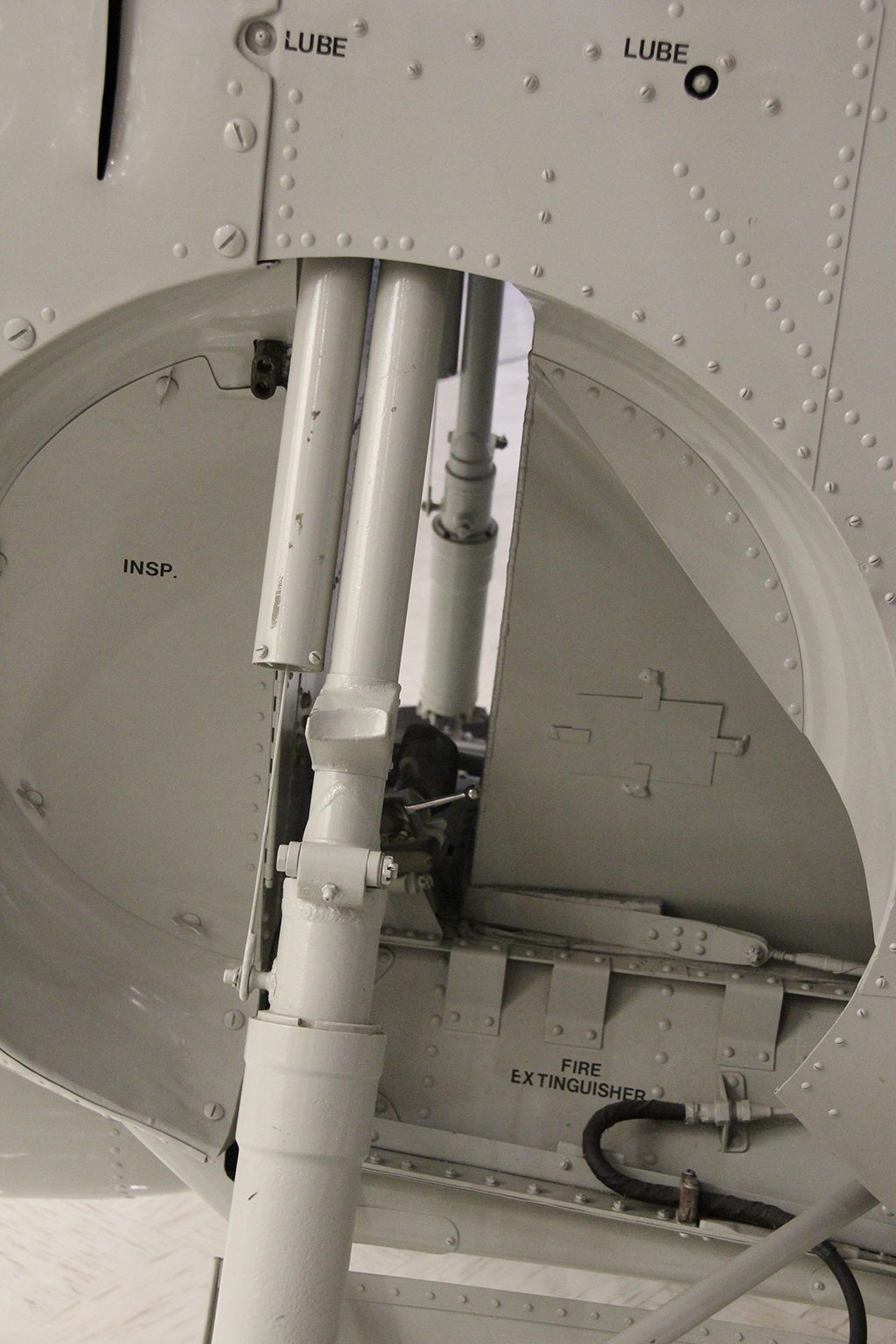
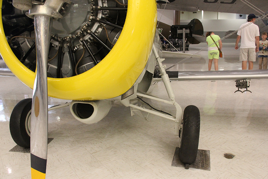
Here is the geometry of F3F landing strut in fully extended position. Shock is made to be in-line with deployment link. It is axially locked and any movement of wheel as it hits the ground will compress the shock axially in-line with the whole upright strut. The lower links simply rotate up and down. Physically lower links braces the wheel from moving around except up and down. It is Y shaped arms, just like with automobile front end.
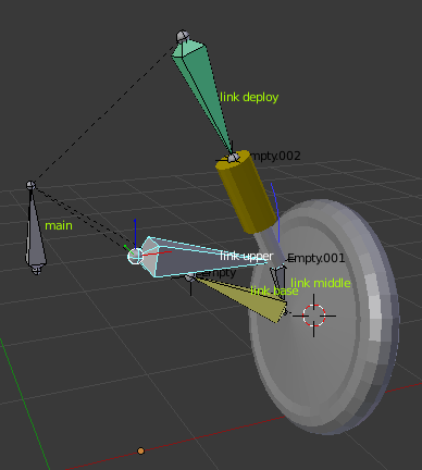
In this simple layout I am using “link upper” to drive the movement of wheel bouncing around. The “link deploy” always points to “Empty.001” as with shock strut. Shock will compress properly with wheel bouncing motion.
Now for wheel deployment / retraction, one needs to drive the links differently. And whole rig layout changes. The “link deploy” becomes the driver, shock becomes rigid link, and lower links just follow. You may be able to workout a solution using FK /IK switch, bu the simplest way to do this is to have two rigs, one with wheel extended, and one with stow / deploy action.
OK - but (there is always a but). On the drawing, the hinge point of the shock to the strut (link-deploy on your model) is offset from the centreline, this is so that the deployment method for the undercarriage is by rotating the strut (link-deploy) outwards and downwards. The strut then stays in this fixed position. Therefore the shock must hinge against the strut when it is compressed. The hinge point is on the outside of the shock allowing it to rotate outwards, thereby opening the angle between the top of the shock and the bottom of the strut. It is physically impossible for the strut and shock to stay in-line when the shock is compressed, unless you also rotate the strut to keep it in line. This was not done on the original aircraft, and is seldom done on any aircraft undercarriage of that time. I think the original was driven by cables (as shown on the drawing), so it would have been impossible to drive the strut to keep it in-line with the shock. Incidently, there is no mechanism on the drawing to show this even being attempted.
I am not disputing your methods or rig by the way, I am just pointing out how the original airplane was built and I think the originator of the thread wants to faithfully reproduce the aircraft, rather than re-model the undercarriage to be more advanced in design and perhaps closer to modern day car suspensions, which do not retract (hopefully!) as they are always “in use”. Bear in mind that aircraft undercarriage is only used briefly in the flight (take-off and landing) and that one of the most important aspects of its design, along with transmitting the take-off and landing forces to a strong point of the airframe, is to get it out of the air-flow when in flight. This was probably more important in the case of the F3F, when the designer probably opted for aircraft air-speed to chase down another aircraft or to get out of a chasing aircraft’s gun reach! The fact that the strut and shock do not stay in line is a fundamental design flaw, since the forces exerted by the wheel touching the ground are not transmitted axially to the strut pivot point as they ideally should be. Some of these forces would therefore have been transmitted through the undercarriage deployment cables to the actuator mechanism, which could have been either and electric motor or hand crank and represent an “far from ideal” scenario, but that was how Grumman built the thing!
Cheers. Clock.
PS. I am not trying to fall out with you over this - just going through the model from a 1930’s aircraft design point of view.
I have been asked to do a tutorial for how my rig posted here was made, which will be my first, so if anyone can advise me on the best way to do this I should be most grateful. My machines are either a MacBook Pro, my preferred option, or my Linux server.
Thanks and happy Xmas.
Clock.
Hello again,
I have tried to do the video tut, but kept making mistakes - kept going all self conscious about the commentary! So I have decided to do a written one on my website including pictures and small videos, which is not ready yet, but here are two videos taken from it. The first is with the original assembly, the second is with a modified, more modern approach, using a sprung hydraulic cylinder, still contained within the original airframe profile. I should be grateful if a Moderator could let me know if such a tutorial could be referenced on this site.
[video]http://www.lafavinie.f2s.com/blender/images/uctut5.mov[/video]
[video]http://www.lafavinie.f2s.com/blender/images/uctut6.mov[/video]
Thanks in advance, Clock.
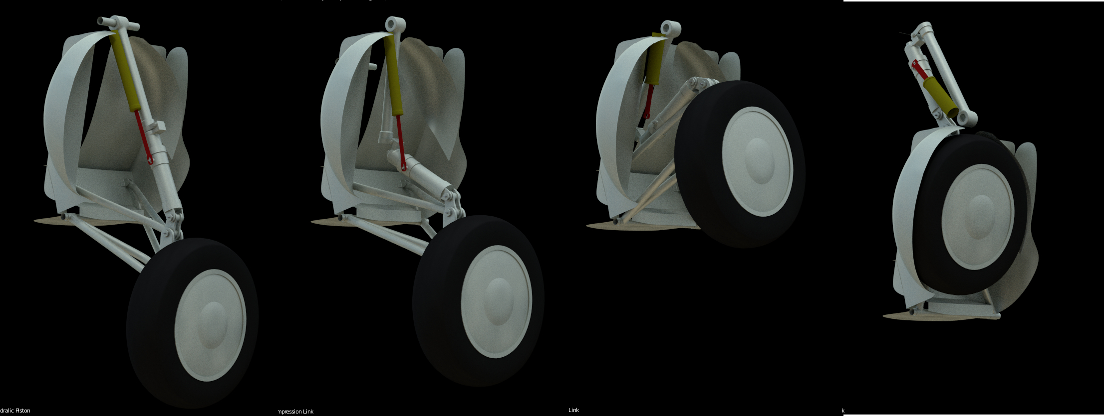
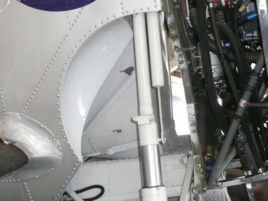
Interesting posts by all. Thanks for the information and comments. Attached is my progress. I have been struggling some with getting everything to fit and align properly and to pivot correctly. I think am I close. In the image set below it shows the gear retracting. These are still shots as I am not an animator, but want to have working gear on this model.
I am having some trouble with the smaller yellow cylinder and red piston arm. I am using one single bone for both and it’s causing scaling issues. What I really wanted to do was have the piston arm stretch to the cylinder AND have the piston arm stay secured to the Oleo Shock Strut. As you can see in the images, the scaling is an issue and the piston arm is not staying secured to the Oleo Strut (see image 3 & 4). Also, I am having to rotate the Compression Link (upper portion of shock) extremely far to get the whole package to retract (image 4). I don’t believe the F3F-1 rotated that far, but without engineering drawings it’s hard to tell.
I attached the .blend file here if anyone can provide any help on the yellow cylinder and red piston arm issues.
Clockmender…you tutorials videos look great so far. Looking forward to the final tutorial.
Hello,
The reason your yellow and red parts are scaling is that you have them parented to a bone with a “Stretch-To” constraint, so they will scale with it. the way round that is to add two new bones to the top and bottom of this bone, which are parented to “Hydraulic Piston” but do NOT inherit scale and DO inherit rotation. Then assign the two meshes to these bones as I have done below:
Grumman F3F-1 Landing Gear Armature WIP-C1.blend (1.45 MB)
The rest is a geometry issue that I will have to look at separately, later on today. This is good progress, but I note the animation runs really slow on my Mac, so I will also look at why.
Thanks for the comments on my tutorial, I will give you the full link once its ready.
Cheers. Clock
Update,
I have also noticed that “Oleo Strut Cylinder” is inheriting scale from “Oleo Shock Strut”, which will cause you problems when you scale the Oleo mechanism to simulate suspension movement & “Oleo Strut Piston” looks to be in the wrong place - I think it should be at the tail of “Oleo Shock Strut” and parented to it with inherit rotation, but not inherit scale.
The speed issues are to do with your subsurfaces modifiers - you have set them to 3 for view and 2 for render, perhaps 2 for view would be better.
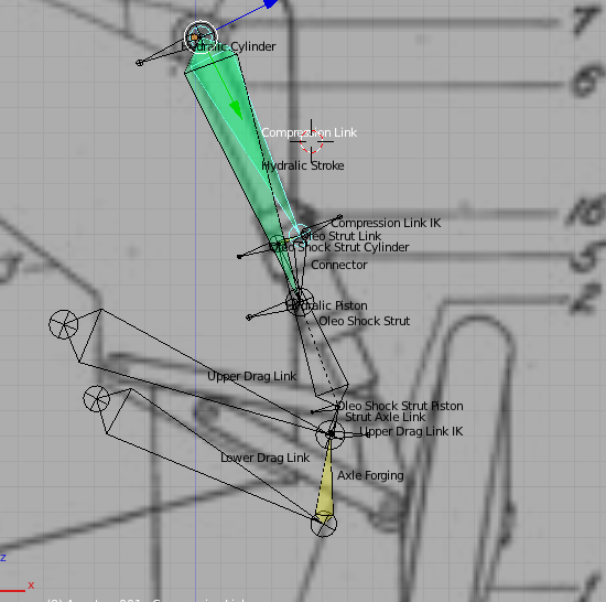
Hello again - just had a quick look - you have some serious geometry issues I think - below is a blend with the original drawing as a backdrop. The geometry works here, but it’s only approximate. See what you think.
uc-geom.blend (486 KB)
Cheers. Clock.
Update:
I have added the landing gear image to your file and it definitely does not fit the armature at all. Therein lies the geometry problems. I had to scale it to size, but the links do not line up with the drawing. Is there any chance you can mail me the images you used to build the model? Mail address below:
Here’s the screenshot:
Thanks Clock. I sent the images. I had trouble getting everything to lineup and fit per the drawings. So my armature is adjusted to fit what I modeled. The drawing you overlayed was an early patent drawing. The actual aircraft differs significantly as far as geometry. Attached below are several images showing view of the gear on actual aircraft.
Attachments
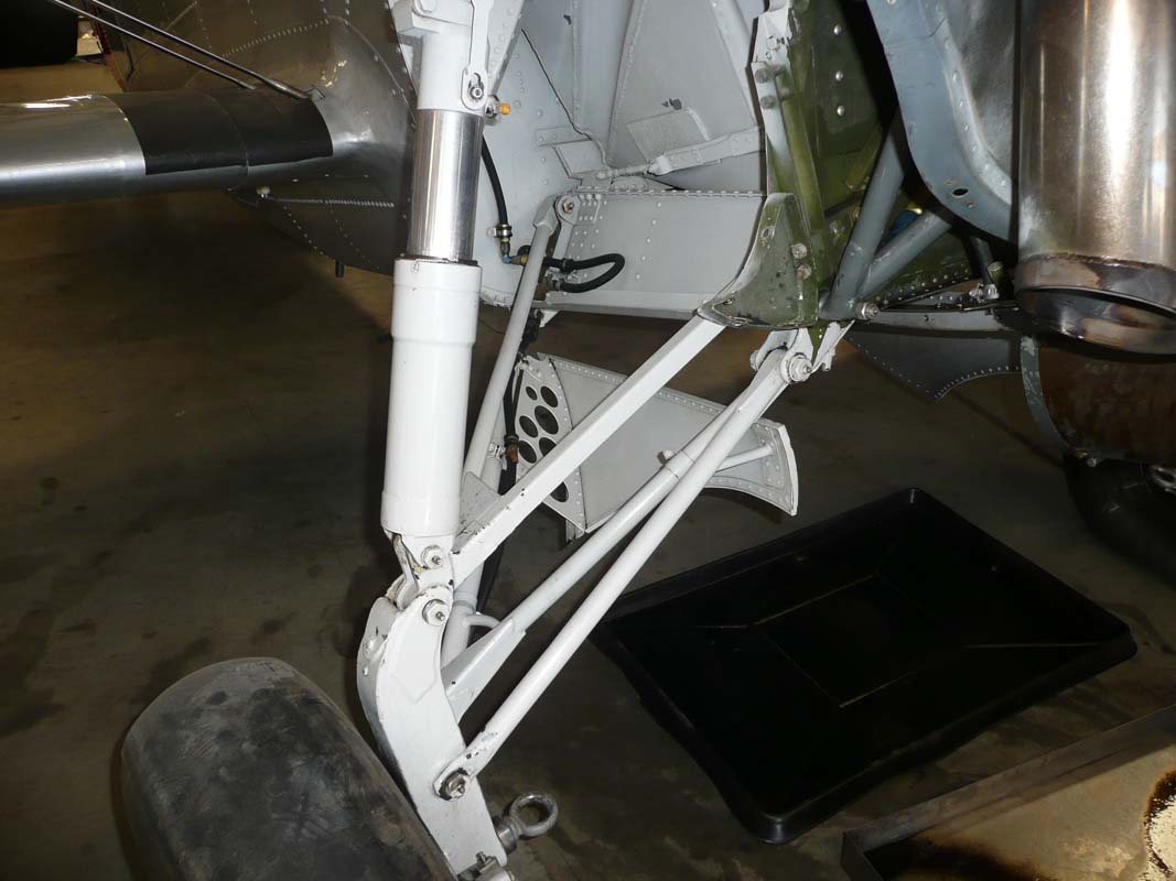
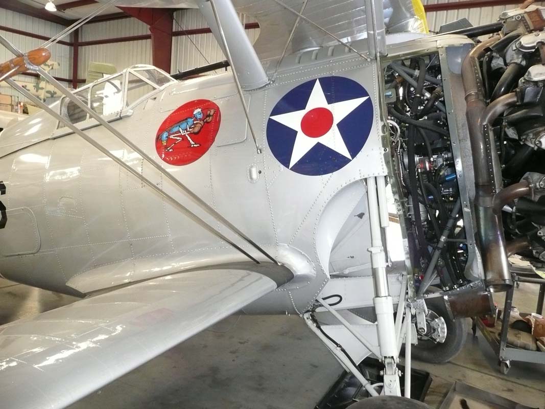
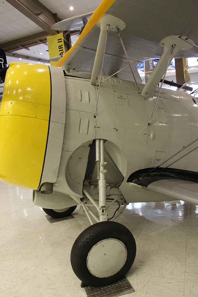
Also, I am modeling the F3F-1…not many good clear high res images of that model on the web. It was a short run before they introduced the F3F-2, which had slightly different landing gear design as shown in images.
OK so now I have it, I think…
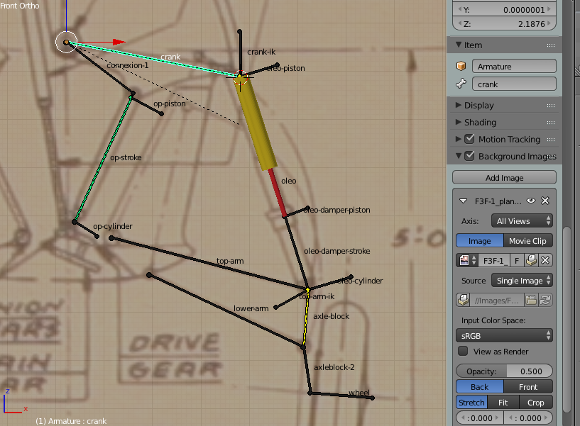
See the attached blend file, Rotate bone “Crank” to retract the undercarriage. Scale bone “Oleo” to operate the suspension. The yellow cylinder is a damper only and damps the oleo strut during suspension movement, I have added this to the top armature only.
There are two armatures on the two front views of the drawing - I see what you mean about anomalies! The drawings do not stack up, so I have put two armatures, chose which one you thinks fits your model best. I am afraid to have to say that you got the mechanism wrong - sorry - but it is operated by a screw cylinder powered by chains from a motor. These drive the “op-stroke” bone on my rig, which in turn rotates the “crank” bone. We use inverse kinematics here so this is controlled by the crank rather than t’other way round. On the real thing, the lower half of this would wind into the upper half to extend the u/c and wind out to retract it. This really was the infancy of retracting u/c’s.
You may have to fiddle a bit with the bone’s head and tail points to fit your model, but don’t change too much or it will not work properly, i.e geometric errors will creep in.
I have had to “pasteall.org” it as I embedded the drawing into blend file.
http://www.pasteall.org/blend/33691
Here’s the pic:
Hope this helps you, let me know how you get on. Cheers. Clock.
Awesome stuff! I recommend to anyone wanting to learn how mechanical rigs operate to take a look at these examples.
The last version animation of the rig I did based on Clockmenders tutelage came out pretty good. If anyone is interested in seeing it, drop me a message. Thanks Clockmender and others!
I have written a tutorial on how I built the rig for this thread, after requests from members here. The tutorial is my first for Blender, so please accept my apologies if it’s lacking in some respects. It consists of written passages, pictures and some movies (Flash .flv’s now, after a request to change the .mov’s!) and is spread over four pages with links at the bottom of each sections for the next page. I hope this will be useful, not only for this specific thread, but for other applications involving similar mechanical systems consisting of chains of links, with some compressive and some rotating parts, where accurate geometry is required for the system to function. I will post it to the tutorials section on BlenderArtists as well, to see if the Moderators like it. If you have any questions, you can contact me via my website, or PM here. I have also posted the final blend file on the last page.
Tutorial is here: http://www.lafavinie.com/blender/uc.html
The Blender side of my website is in its infancy, so please be patient as I develop it further. Any suggestions for improvements will be gratefully received. I did try a complete video tutorial, but failed with the commentary - repeatedly!
Cheers. Clock.