Thanks for the screen shot Craig,
I am still digesting what I’ve been shared with earlier. Thanks for the clarity on the dom/top layer/input ‘green dots’. Although they are not used in this pic… Well they are, not just not the purple shader you are now sharing with me. Which will leave me to revisit this post after getting a feel for bumping. Right now that post and the terms used; composite~ Texture Image Node…(I’m thinking?) You know…need to be clear in my head.
For instance you share a great node path…To you it makes clear sense what is happening and why… To me it looks like a bunch of nodes I am still foggy on the nodes affect on the information of the image texture (or composite as you call it)
Well at least I know what some of em are doing, not like 6 months ago where My head would be swimming. Maybe if you got the blend file still there, you could send me a full node map shot of the one’s cut off too?
Thanks again,
NC
I don’t have that particular one on this laptop, but here is one I was working on the other day that I experimented a bit with iterations of a stencil…
edit: here is the video on my youtube channel that explains that particular file, maybe that will help a little.
That is a “created group” of nodes? Nothing that is ‘canned’ needs to be created?
Would you rather hold a PCB and move finger above the LED to move cursor on the screen instead of holding all that wire and component mess included in nice shiny mouse plastic casing? Bunch of nodes can be “canned” into the Group (select, Ctrl-G) providing finite functionality and easy sharing between the files. If that was the question; i feel lost a bit…
Digital paint is all the numbers - add, subtract. Multiply is add several times, divide - subtract… In fact, it is even worse than that- they use zeroes and ones only ;).
Probably the main impetus for “named node-groups,” and for the ability to “link to” such groups in other files, is a pure data-processing consideration: “if you need, for whatever reason, to change ‘this thing,’ you need to be able to change it once … such that the change then is guaranteed to take-effect everywhere else.”
Fact is, that’s the fundamental idea of the entire “linking” system. A real-world project can quickly involve a rather ridiculous number of files … and “all of them need to be consistent.” How do you accomplish that feat? By defining whatever-it-is exactly once, and then referring to that definition everywhere else.
Craig thanks for the follow up heading over to the video now.
Jandress-thanks for the chocfur site. It was a great read on why and what instead of a just do this and that. Really helped.
Eppo- Yes analogy of mouse got it. That is a Node that is a group initself, I will only need to cipher all the nodes in it and create one myself. I do not think a node group is a universal thing though. Where it can be saved for other projects… can it?
Sundials- Yes universal change is good within a project, but not always wanted. If that is what you were philosophizing about??
Thanks guys, one step closer to understanding that Shaders are a culmination of desired textures combined to create a certain look, be it of this world or not… One shader although named Glass is not necessarily glass, rather a base for creating ‘a glass look’ to then be enhanced, enriched and manipulated to then be Sold to the viewer as “Glass”. Where FAC, Roiughness, Layer Weight, RGB Curves amongst other shaders are used to “Sell-it”. That last part is where Chocfur’s website was helpful in that regard. Thanks again Jandress for that link.
Now it is a matter of connecting and adjusting where every adjustment creates a different result…
Point is Blender allows simple copy/paste of most of the things from one opened file to another, however one can use data in other file without explicitly opening it. Nuance is - some prefabricated nodes can be transferred in this manner only as a Group. File - Append does that and you need to choose something from Node Tree folder. Best example of such library probably is here shared by Sebastian Röthlisberger aka bashi.
In the file you work appended node groups are found under the Add menu in Node Editor.
Most often used ones can be saved in the default blend file.
Technically, basis of every material i use is a mix of two BSDFs driven by Layer Weight so it makes sense to keep group of at least this. While change to one Group makes other groups copy that setting it is valid only in the range of one blend file if the group is appended. Link is another way of transfer data - it is assumed that if you change original linked copies change too. From my quick tests node groups do not update- i might be wrong. As always - click on the node’s Users number box makes this group unique and tweaks there do not mess up other “same” groups.
Color and how the light hits back are two main ingredients: color nodes and BSDFs; the rest is just a helpers you can send anyone do anything.
Thanks Eppo,
I just downloaded the Blend file. I will take a look at it and do as you suggest. File>Append to open as a blend file in a project and then copy and paste Node Groups as desired.
back to the thread on this one. I have not worked on you blend file you sent other then checking it out. (not recreating for my use)
I did however watch Craigs video (too many different types of maps to follow for my own simple bump)
Craig I had tried to follow your tut twice before and ended up with some questions with no resolve. Prob my novice and not getting it…
I read JanDress’ links to Chocfur and kinda got this out of it, although I am not seeing much of a bump (when moving my light around)
and about lights I would like to see a better glow off my lights. Any suggestions on which nodes to use with which map?
Spec map that is B/W into ??>into??Into??
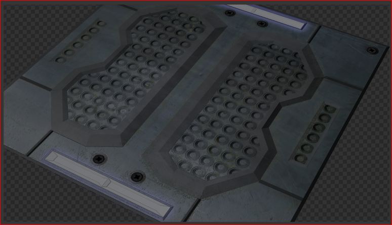
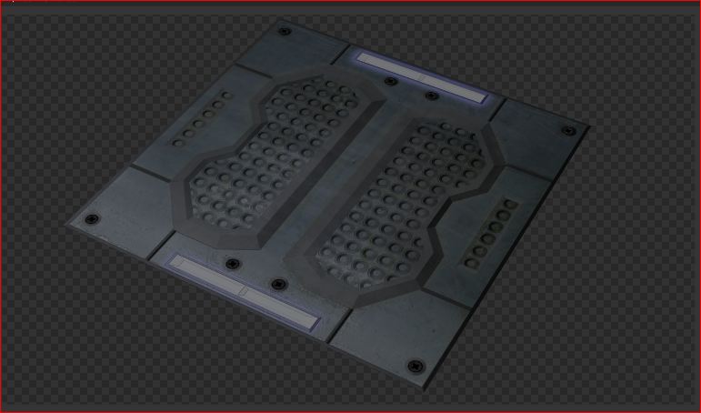
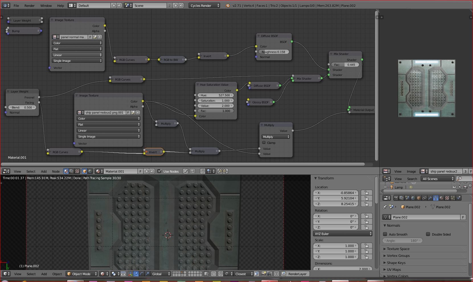
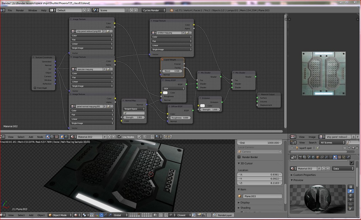
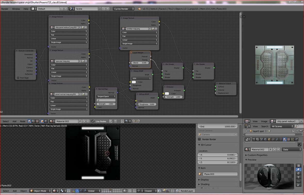
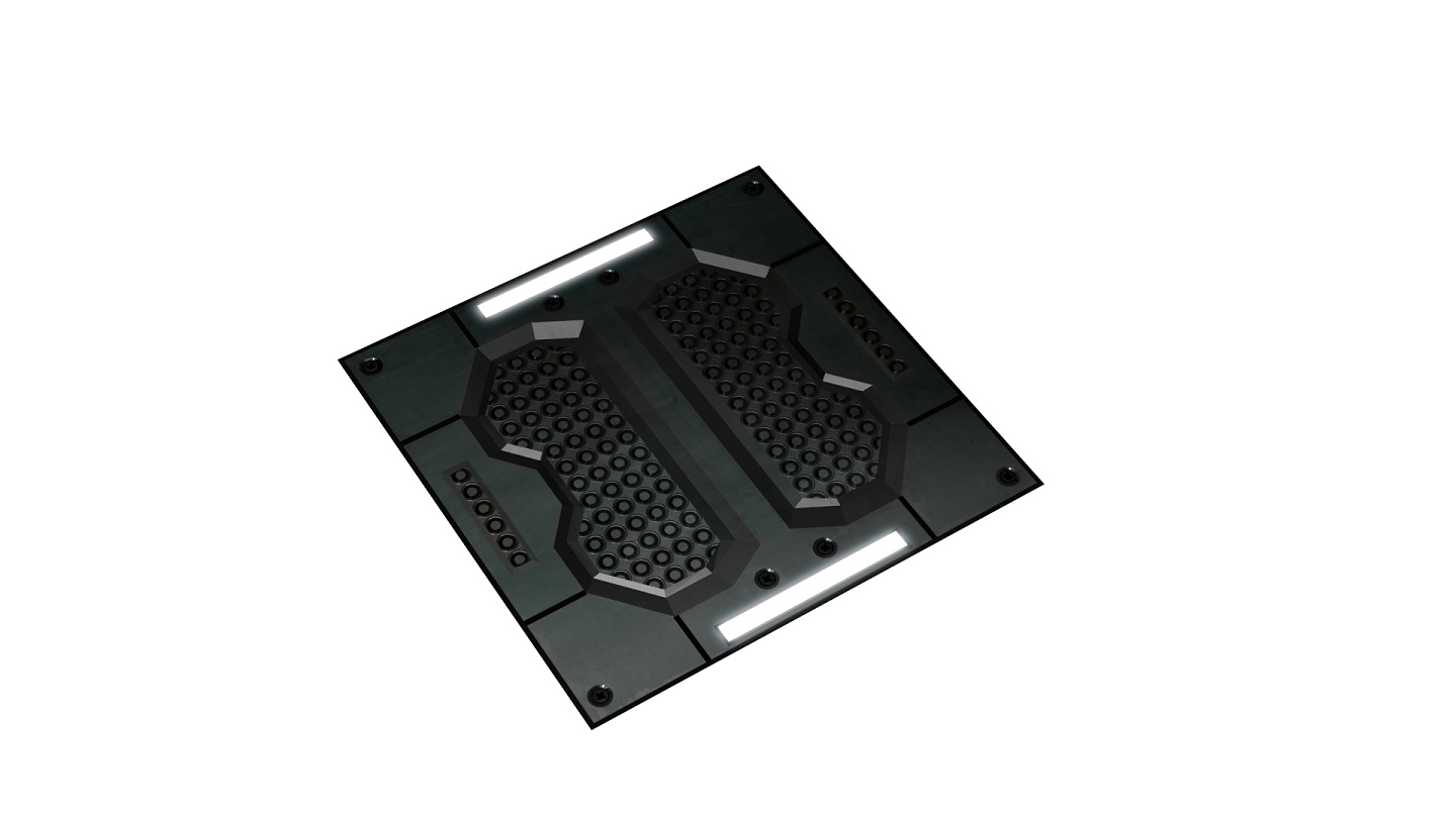
Here is a grab of my tree and the two following is the render with only the light moved in X axis on one side to the other…
For starters, disconnect the layer weight node feeding into the vector input on the normal map texture node. Also, the normal map texture should go into the color input of a normal map node, looks like you have it going into a bump node? And even this bump node is not bumping anything as it is not connected to a normal input on any shaders.
Also, there is no actual shader going into one of the inputs in your second mix shader node.
Thanks for stopping by and helping Jandress
So that top Normal Map run should be RBG Curve to B&W to Invert then to a Bump into a type of shader (like diffuse?)
Which is one in the same as this statement? “Also, there is no actual shader going into one of the inputs in your second mix shader node.”
A normal map does not go into a bump map node, and there are very few colour adjustments that make sense on a normal map. Put it into a normal map node. (under the “vector” category in the add node menu or sidebar.)
The output from your normal map (or bump map) should go into the vector input on all your BSDF nodes (unless you are doing something like a material with a clear coating where the coating layer does not get the normal/bump.)
Something else to think about as you are building nodes: The colour of the connector pin is telling you what type of data is going through the noodle. A yellow dot means colour information, a blue dot is vector information, a grey dot is scalar information, a green dot is a shader connector. You don’t want to connect anything to a green dot besides another green dot. For the other types, a conversion may take place even if you have not explicitly added a converter node. (So if you connect a colour noodle to a scalar dot, the data will be converted to grayscale automatically.)
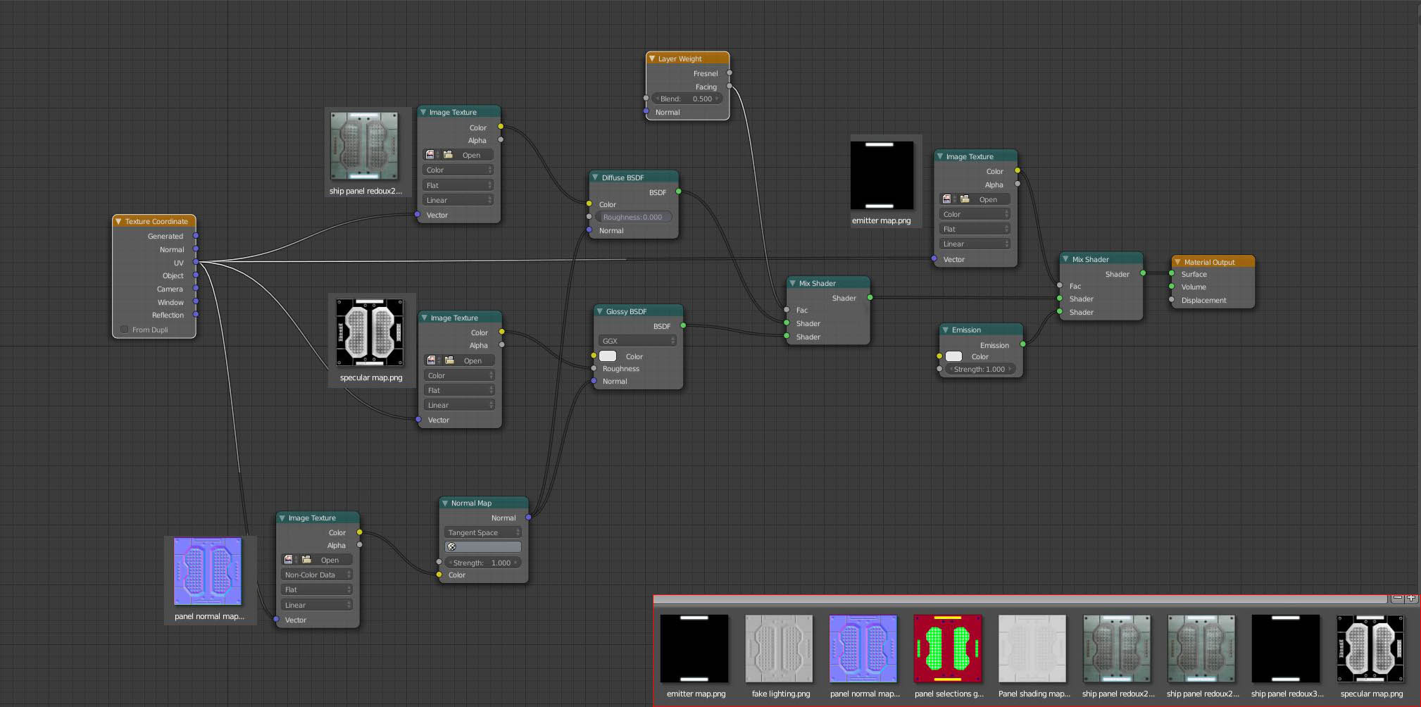
The first mix shader gives you an emission material for the light panel.
The next one gives you both a diffuse and glossy component for your metal. The layer weight means it will be more glossy at steep viewing angles. The specular map into the glossy roughness is not the best setup but it is a simple way to give variation without adding a more complex node tree. Note that the normal map is set to non-color data. Also, if you leave the vector input empty on a texture node it will default to UV, which is what I have shown here with actual nodes.
Also, lights emit but they do not “glow” unless you use volumetrics, or as a post process in the compositor.
Jandress,
I got an opportunity to try your tree out. Really good, layout. Very light dependent and how it reacts.
IE: Moving my model past a light source, would def show a lot of contrast and give a motion feel. The emitter map really works.
When I use numpad 7 for a top dead on the rest of the panel is blacked out except where that emitter panel is assigned. Is there a way to adjust that to NOT black out completely? More of a color still visible? Or is that one of those dealeo’s where if you want light to react to a texture then it goes black out in certain angles…Take it or leave it…
Although the other attempts gave a bit more bump to the panel where the grate is (for a lack of better term) see post 31 top pic where the geo detail is in the center appear a bit deeper then the set you shared. Is there a way to get a better bump in that area?
Thanks again for that tree, I will study it and play around with the settings to tweak it out a bit…Appreciate the tree and everyone’s help and time on this one.
flipped it to a point light and adjusted the emitter panel a bit more…
also used f12 out instead of a screen grab of the render, albeit a tiny sample of it.
[ATTACH=CONFIG]346169[/ATTACH]
Consider this is a Plane you’re dealing with, flat thing from the point of view of the math involved. And probably some sin, cos or even worse - arc functions hide around. So any corner case will be off. It is supposed to be off, kind of. Same goes to flat light, dead on top or sideways below certain angle.
Now, the flat light: normalmap is a cheat. Cheat is blended in and not so visible from the certain angles - light is one thing which makes it blend in better - Pointlight. It’s light starts from one tiny spot and goes all directions, hits what normalmap says to reflect and blends in it’s monotones and flaws. At least it should be like so- in the plain Cycles reality it’s other way around, different story.
If it is mathematically correct parallel light beam… it’s different, closer to the math and not pleasant for the eye.
There’s always limits to cheating.
What are you reflecting from that flat plane, btw? Light from the Point, Spot, Sun and what else? Black or gray Blender’s default? Try changing it into some Environment light, HDR image containing surround information. Change Blender’s World if you see some definition on that normal mapped plane under the Point lights you swing above the plane to better see normalmap’s influence.
Making surface rough and changing light can help to step back that black or bright white. Less Glossy, more Diffuse. Here you start to loose on the normalmap’s effect so this is all about finding a compromise; you decide where to stop.
Oh, and greens to greens on the Nodes. There’s no way around, sorry i did not mention it earlier. Green dots on Nodes, i mean.
Eppo,
Thanks for that info, I will see how it reacts to adding some ambient ‘noise’. Yes, right now it is a lonely plane in a blank Blender world.
Glossy and Diffuse are my adjustments there… I also suppose I could use a Math Node to double or multiply the map I want a bit more out of.
I am going to mess with your Blend file you sent and revisit Anthony’s tree. Blender is a real cool toy and I was Naive to think it was a cookie cutter approach to texturing. For some reason once you edit a post the added attachment is no longer valid. That Lonely plane I mentioned: Via Jandress’ Tree Looks good IMO
Jandress node tree is perfectly correct and does include all your image components except that now you are to adjust b/w levels and contrast in the last image in the image strip below the nodes - one which plugs into Glossy Roughness value. I mean you have to do this in image editor after you find out that something is either too shiny or too dull on the render which is a bit inconvenient… This would be where i add in some level adjustment node or two.
Also, you can’t increase normalmap’s image effect by any other means than remaking it and even then it’s limited in what can it achieve. You can boost slider’s value behind 1 but usually that causes black artifacts and doesn’t look great.
Regarding your top view issues - when you hit numpad 7, I believe by default you are seeing an orthographic view (all the camera rays are parallel). This will lead to odd effects in some situations. If you hit numpad 5 you will toggle between orthographic and perspective mode.
Bump and normal map effects will always break down from close up or at extreme glancing angles. They are a cheat to reduce computer power required for a given result. If your intention is to create high quality rendered images, rather than creating game assets or needing very fast render times, you should consider using actual geometry, and only use bumps/normal maps for very small or far away details.
Eppo thanks for the further tips on the B&W values. I did go restudy that blend file you sent… Wow! Groups inside groups man; an orgy of nodes going on in that one buddy. I think that is a bit advanced for me to even start to know which ones to use, and where. I will hang on to it and revisit later on when I have a better grasp on this texturing with 3 different types of images and what is relevant to which value.
Jandress- Thank you for hopping back in here and you are right I am using this for motion graphics and not a still where Geo would be optimum. However since I am on a reg W.S and do not want to wait for 2 hours per frame to render. The resolve is the path you all have helped me on. This all started with Eppo pointing out a 1.5million vert face grid floor of my shuttle. I just want to make movies man! LOL!
Thanks for the tip on NP.5 for previews.