Ran into the same problem but came up with a different solution (gonna try this approach as well, though). I made a wood floor with some nice ups and down on the boards and when I baked it as Ambient Occlusion I pretty much got what I needed. (Memo to self: remove any reference figures on the floor before you do the AO bake unless you want footprints in your map).
@grinsegold Yes, you did get it right. The displacement socket can work ok if you have a bump map (greyscale)… But if you have a normal texture (vectors) in world coordinates (as Cycles use them), then the bake result will not be correct. ![]()
In the example from my first post, it’s simplier to connect the voronoi texture to the displacement socket and bake it. However, there are situations where you produce normals based on vector calculations, and there’s no bump map involved… that’s why this node setup.
First, I don’t ‘insist’! If you don’t want to use it, don’t; I really don’t care! I build this node because I needed it, and I just shared it here, because I’ve seen people struggling with the same problem.
About the color management, your are totally correct, and it was something I totally forgot to mention. It won’t make the normal map crisper, but it will store the normal values with their real values. ![]()
Anyway, thanks alot for noticing this (apart from the tone you use)
Probably a stupid question but, how do I bake procedural generated textures? (like diffuse and spec and so on…)
Thanks in advance!
If the texture (procedural or not) is connected to a diffuse shader, bake the diffuse color. The same goes to specular, emission etc. ![]()
Thanks a lot! ![]()
Hm, OP, since you seem to understand this type of thing, maybe you can answer me this: is there a way to convert to and from UVW space? (the same way Object space is aligned with the object’s local X, Y, and Z, and World space is with the global X, Y and Z; UVW space is aligned with the U, V and Normal axis of each face)
Long story short, I’m trying make a noddle that does parallax mapping (just wanna see if I can do it).
The way I was thinking of doing that, would be to get the dot product between the incoming ray and the U, and the V axis, and from that, plus a depth map, calculate how much to displace the texture; but the issue is I haven’t found a way to convert the incoming ray direction into UVW space or convert the U and V axes into World space.
I can get it to work for a single flat face as long as the object isn’t rotated; but that’s only because under those conditions I can manually define the values to match the U and V axes.
you may try with the Tangent vector and Normal x Tangent (cross product) vector… you’ll get the directions of U and V in world coordinates.
(at least theoretically… I suspect some cases V may not be perpendicular to U and then the cross product between Normal and Tangent will not correspond to V)
And for a parallax effect, i suspect that you’ll need also some scaling factor…
Another possibility, would be to do it in OSL. since you can retrieve the UV coordinates from traced rays, you could easily probe the geometry in the -I direction to get UV’s from potencial ‘stops’ and use them to read the depth texture.
Hm, that won’t give me the info I need to calculate the displacement in the U and V axis, will it?
Yeah, I was thinking of using a grayscale depthmap for that (if I’m understanding correctly what you mean by “scaling factor”)
I’m not familiar enough with OSL; would need to keep checking manuals and stuff a lot to get even close to getting anything done ![]()
With those vectors (plus Incoming and Normal) you can find the line in UV space where you need to check for stop values (in your depth texture)
Yeah, I was thinking of using a grayscale depthmap for that (if I’m understanding correctly what you mean by “scaling factor”)
Since Tangent is a normalized vector, you don’t really know how much should you probe in your texture. For example, you may know that the U axis has some world direction and if the point being rendered has a [0.3, 0.3] UV coordinate… So you know that from that point in the U axis direction the U coordinate will raise. But you don’t know how much! the next pixel can be 0.4 but it can be anything else.
The problem is that you need to know how much the uv changes, to check in your texture if you let your Incoming ray ‘go’ a bit further or to stop.
I’m not familiar enough with OSL; would need to keep checking manuals and stuff a lot to get even close to getting anything done
If you’re comfortable with programming, then I’d recommend you to take a look to OSL, as it is in fact quite simple… but if you still want to try with only nodes, you’ll face some other limitations (and for a parallax effect, not having loops in nodes may a the stone in the shoe). ![]()
Maybe I’m using the wrong term; I mean I’m trying to make that effect where things that are further away appear to move slower when the camera is moving side to side (or moving in a circle around it, or everything is rotating). I understand there will be some artifacts at shallow angles, but if I don’t make the depth difference too big, and don’t look too close, I don’t think it will be all that noticeable.
edit: Erm, in the case of the orbit/rotation scenario, things only go slower when they’re closer to the center; if they’re past the center they start getting fast again. Not too important for what I’m trying to do, but someone would’ve pointed out that little detail sooner or later.
uhmmm… well, if your object is very simple (i.e. a plane) you can use something like this as UV map:

The factor for the RGB_Subtract node will change the depth distortion (0 will keep the texture at the plane level, and bigger values will make the texture to appear as if under the plane)
This however, is not so correct… it can be used to fake some depth in stacked textures, but will lack of proper illumination and the perspective will distort exponentially.
Ah, awesome! That works, thanx! ![]()
I think I might need to apply it to the depth map as well, so first distort the depth map, and then use that to distort the texture itself.
I’ll let you guys know when I figure it out.
Hm, I was expecting it would have some smearing caused by interpolation when looking from an angle that exposes a sharp height difference; but instead I’m getting gaps and repeated “layers”…
Any idea what could be happening? (if just be the description you can’t picture it, lemme know and I’ll clean up the noodle and upload the file as soon as I manage to)
edit: Hm, separatedly, there is also an issue with the texture slipping on the “model”; I’m not sure what I’m doing wrong; it’s a bit of a mess and I’m not sure how it works in the first place…
Those are the kind of behaviours I was predicting.This method has a long list of caveats (and that’s why is notso much used) depending on your scene, some modifications must be made, sometimes a total rethinking.
If you don’t mind, pm me your file, so that we stop hijacking this thread with an unrelated topic 
I have a feeling 1/depth and/or atan2 belong in there somewhere; still trying to work out where exactly. If this starts to look like deadend, I’ll create a separated thread and send you the link.
can you post link to math that u used here ?
Here’s the formula:
result=([cos(Nw, U), cos(Nw,V), cos(Nw,N)]+1)/2
Where Nw is the bump vector, N is the original normal, U is the UVmap tangent, and V the cotangent.
The cosines are from the angle between the two vectors inside the parentesis. As those vectors are normalized (or should be!), I used the DOT product, since dot(A, B)=cos(A^B)||A||||B||, where ||A|| and ||B|| =1.
This is awesome and I don’t know how you came up with it but :
Are you sure ? Then why is there a World Space option in the node ?
Also, can you explain why your node group makes a brighter result than the original ?
In the example below , I used an already baked Voronoi texture (not a procedural voronoi) that was baked with Blender Internal and plugged it to the color (top image). Then between the two I put a normal map node followed by your node group and set the Image node to “Non-Color Data” (bottom image). Shouldn’t this give the exact same result as the original if your node group did the exact opposite of the Normal Map node ?
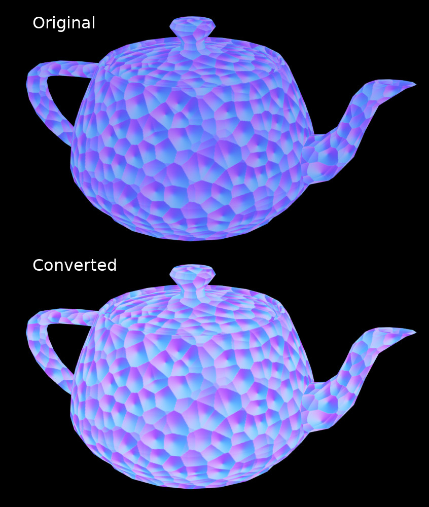
You can also see on your original post that your baked texture is too bright (it also has some almost white spots which shouldn’t happen in normal maps).