zoom in and just scale the tire a little bit
can you show the object pattern you use for the array !
looking good
happy bl
zoom in and just scale the tire a little bit
can you show the object pattern you use for the array !
looking good
happy bl
I used 2 curves and a array, i thought i use a empty and spin this. But cause i used 2 curves i would work, bit stupid  But i cant get the middle to connect properly, the setup is quite simple
Bend Tire.blend (188 KB)
Sorry i got it now, editted the crease of the main object. if i apply all i get 198k per tire if i set the subsurf to 1 its just 10k so baking a good normal map would help tons here. Hope its helps, like to do something for this forum cause they alway help me as well
Bend Tire.blend (190 KB)
nice trick with 2 curves
because of the longue shape for the pattern it is difficult to do it with only one curve
what is the pattern on the left ?
it is not use on the modifier list !
is there a driver on the pattern ?
I remove all modifiers but when I try to move pattern it is going back and forth a little!
if u apply all modif for tire - it has 161 Kverts
big high res tire!
happy bl
Elegant work with the two curves! I gave that a shot but encountered some oddities I can’t recall now but never thought to build that small curve as a tire profile with the flatter interior.
I might have left out or not been clear that the 500K count came from 5 subdivisions - I forgot to explore economizing the poly (polyconomics?) count with fewer subdivisions. With the real tire being almost five-feet across, I knew it had to get some attention to detail. I think it makes the treads about 2-inches deep.
In my tire trials, I also had trouble Merging with the Array Modifier and saw some misbehavior with the ‘first and last’ despite careful re-editing to have the two pieces meet.
I eventually went with the Displaced method on these tires because, most importantly, it was the easiest way to control the depth of the tread without altering any geometry. If another detail has to be added, I can just alter the image.
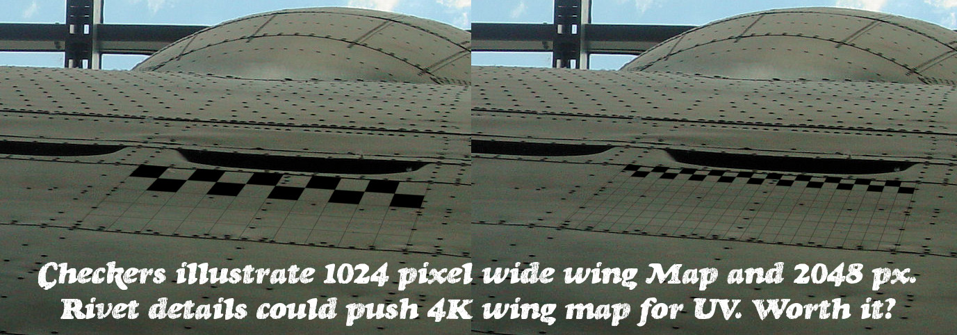
MEANWHILE, on the port side…
For UV sake, each wing at 2048 pixels across means that some of the closest appearing rivets must be drawn/painted every other pixel to even come close to scale. Naturally, or 3D’ly, a one pixel rivet lacks some interesting detail and as a bump is possible, but clumsy. Just how wide should I consider making the more detailed Maps?
A labor intensive idea could be to break the Wing UV into polygon sections with high rivet count areas getting hi-res UV Maps? Is that a better idea than just going 4K per wing?
@ RickyBlender, that part on the right was a earlier test and a backup part. Its not used for anything. This model of the tire is pretty difficult i think cause of the diamond shape mixed in a round and a oval shape. Pretty hard to pull this of nice. I was just testing and see if i could replicate it and make a better version. Like i said if you push the subsurf down to 1 the tire gets around 10k
@HelloHilHola, if i understand you well you want to align the pixels with the mesh? Is this normal in 3d cause i never heard about this. I believe higher maps are for more detail and lower maps is for better memory usage. It all depends where you want the model or render to be used for. I also think 1 map is for easier work but lower detail. Cause if you cut the wing up in sections you could get higher details but more work linking everything and more maps are going to be loaded in the memory.
I agree with rombout: pack the UV layouts of all the meshes of the outer skin inside one area. It allows you to draw the bump maps, diffuse maps, reflectivity maps, etc. as single images. Do not worry about the pixel details in the close-ups: If you want increase their resolution in a particular area, just increase size of corresponding UV faces on the layout. For example, if your camera will be placed in the bottom gun capsule, you can enlarge the size of UV layouts of the faces from the wing root area. Then you can draw larger, nicely shaded rivets dots on these enlarged panels. For example see a model of similar “size”: four-engine bomber, made by Piotr Forkasiewicz. It was created a few years ago (2010). In that time our computers were less powerful, so he used one texture for wings and nacelles, and another for the fuselage. Both of them had size of 6000x6000 px. However, I suppose that today he would use a single larger texture of similar area - for example 8192x8192px…
I read somewhere thats its always best to use maps by power of 2.
power of 2 is valid / must for BGE !
but also easier to work with !
happy bl
PS that link with the images of those planes is awe some! That fella got some serious skills!