I have seen it, and i still advise everyone that don’t require a so physically based result to use your method, as the result is pretty good for a normal project. (specially if you have deadlines ;))
Basically this works as an extention of the reflection, and should be mixed with a glossy or an anisotropic shader. But for a better understanding how to use the nodes, i think it’s better to explain what’s really happening :eyebrowlift:!
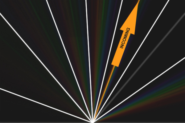
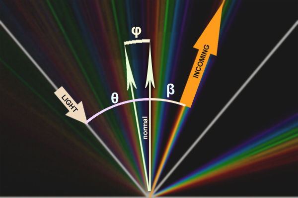
In Diffraction Grating, besides the normal reflection, the interference created by the slits on the surface, result in bands that are visible in directions that don’t correspond to the reflected vector for that surface normal. And to make more complex, each wavelenght from a light ray gets reflected in one particular angle… (well, they get reflected in all directions, because it is still a rough glossy surface, but the interference makes them only visible from specifics positions).
Because the wavelenght is one of the major variables in the resulting outvector, this makes a rainbow of colors, where low wavelenghts are more close to the true specular vector (that is actually the Order Zero), then higher wavelenghts. Also, because the wavelenghts are cycling, there can be a second order of diffraction and a third, an so on, each of them represented by a rainbow.
The number of orders depend basically from the distance from each slit. Low values (400-1000) give just 1 or 2 orders, higher values give more. So one should take that in consideration when using the node setup.
From my last experiment (before my computer broke down :() I found that using the DiffractionGratingLambda for each wavelenght, is quite memory expensive, and has the problem that, if we are not using a big anisotropic effect, the rainbow appears broken, jumping from one wavelenght to the other.
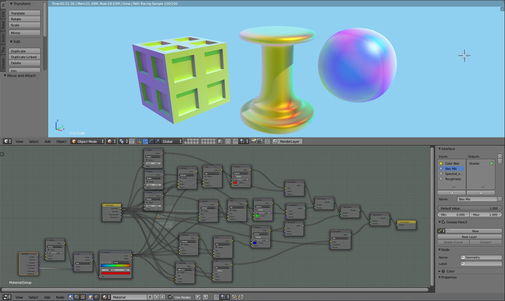
A better approach was to input a random value into the wavelenght slot, and use just one DiffractionGratingLambda node for each order.
This can be a bit noisy with low samples, but it’s faster and more accurate.
For the Randomness one can use a noise with a very high scale, and then multiply by 600 and add 300… This should give values from 300 to 900, which is around the visible spectrum.
Another thing of importance, is the vector for the grating (the tangent vector). It’s around this vector that the shader transforms the new normal, and for a good control of the final look, it’s good to have this correctly setup.
(i’m still installing a new OS in my pc, but as soon as possible i’ll post some usefull materials)
but if anyone still want to experiment, here’s some usefull info:
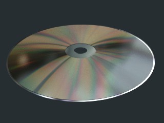
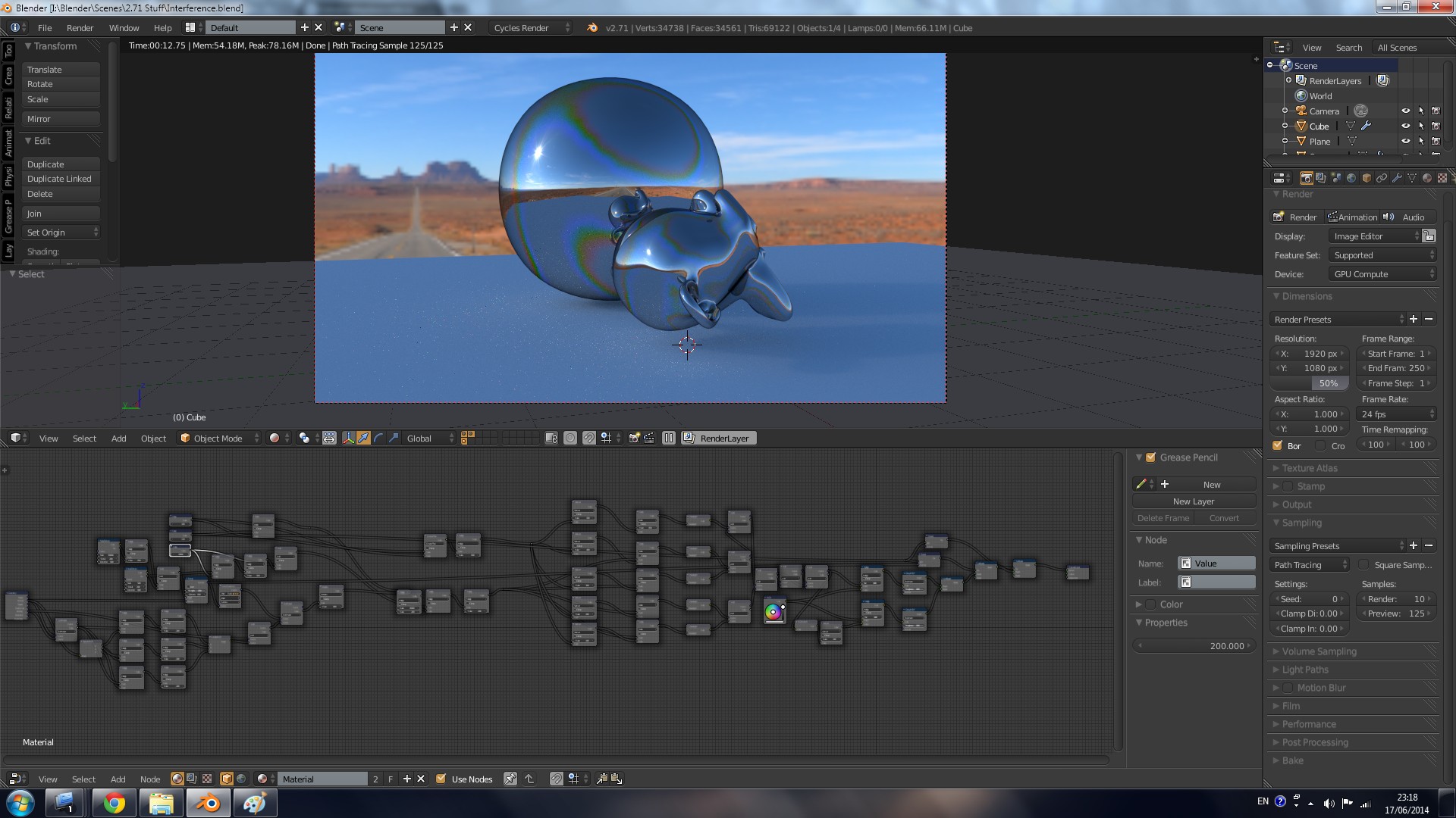
-CD Material (just the metalic part):
Distance is around 1600, N can go up to 3 or 4 (one node for each), Tangent can be the default. And everything mixed with an anisotropic shader.
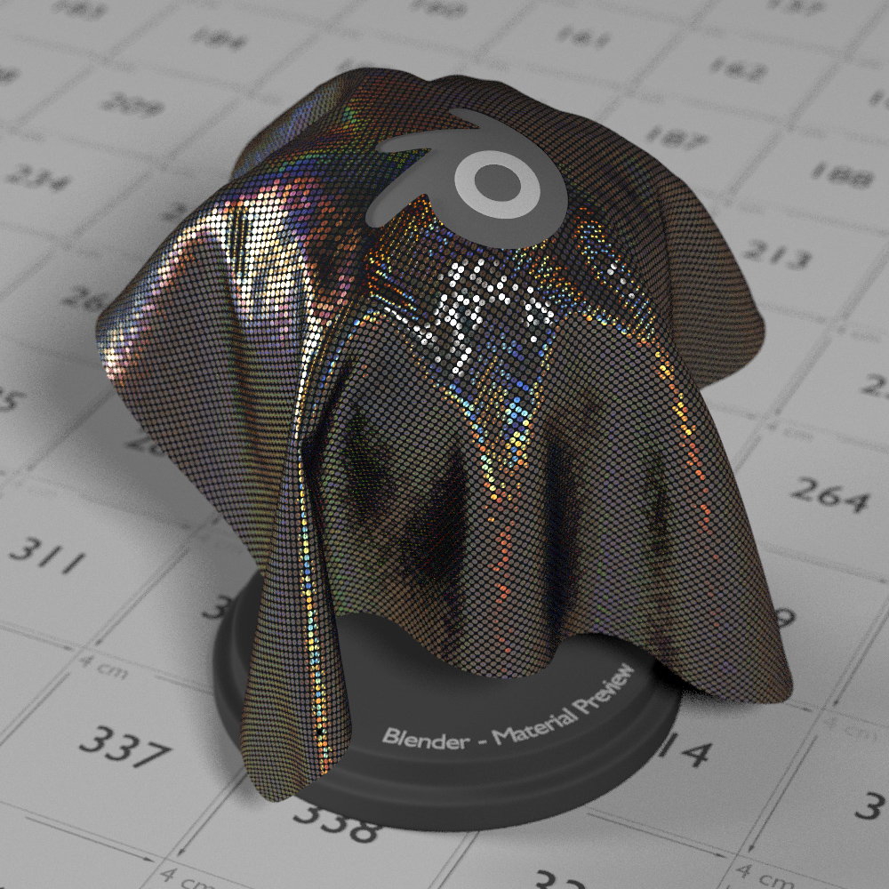
-Holographic Material
Distance is around 700, N can be up to 2 but 1 is ok, Tangent is variable. One can use a voronoi cell for the rotation of the tangent, or if for example you are trying to replicate the Holographic patterns in a 50€ bill, then a Texture map should be made. With a lamp, you can check the tangent vector of each shape in the hologram and accuratelly reproduce it in blender :).
-Feathers and Butterfly wings
distance can vary from 400 to 900. Just the first order is enough. But the tangent should be more elaborated. Low values for the distance, result in a blueish velvet specularity.
I’ll make some graphics explaining a bit more how to control the results as soon as I have my pc up and running.


 five days without Blender and i was already driving mad!!