BGE Advanced Physics Library [NEW = aerodynamical drag]

Hi! I decided to compile my new physics knowledge to create a database of multiple physics concepts. First one I made here is aerodynamical drag.
[videos]

[download]
Physics Library 0.01

[current features]
Aerodynamical drag force:

  • Seperate for each axis making(for example) a flat plane fall faster when facing it’s edge downwards faster than if the face is downwards.
  • Customizable values(drag coefficient and surface area on corresponding axis)
  • Dynamic environment density(property dependent). A demo contains transition between air to water
  • Easy to use, follow comments:)

[updates]
0.01:

  • Fixed drag working in single axis, not it works in both

I hope you like this idea and resources aviable above. If so, rate this thread ***** and tell me so that I have a reason/motivation to add more features;) And come here with your requests for other physic stuff(don’t ask vehicle wrapper, I had the idea of this during creation of it…:D)!

OK! For some reason bugfix didn’t save before. I reuploaded a fixed version!:slight_smile:

Does the shape of the object affect the drag?

Oooh that looks interesting! : D I once wrote a script to calculate an objects surface area, while splitting it into 6 directions(+x,+y,+z,-x,-y,-z), depending on normal of the individual faces.

I’m guessing that’s what the properties you’re altering in the video represent? And am I right to further assume that they’re shifted depending on the trajectory and orientation of the objects? : D ?

I never got even close to where you are on my Blender Aerodynamics Quest : P It’s inspiring to see another work, but better yet succeed! - in that endeavour : D I salute you!

If you ever need a simple way to work out the floats representing the surface area, instead of guestimating them, here’s the code I wrote : P :

########### Script: Aerolyze Mk1 
# Author: john_tgh
#
#
#
##########


import bpy, time, os


path = bpy.path.abspath("//",start=None,library=None)
print("Path: ",path,"
")
path=str(path)
debug = False


x = time.time()


#Makes it so the currently selected object in the viewport
current_obj = bpy.context.active_object


#ob = bpy.data.objects["Cube"]


#Defining the function that distributes the area of individual faces into
def facecheck():
 areaVector = [0.0, 0.0, 0.0, 0.0, 0.0, 0.0]
 totalSurfaceArea = 0.0
 if debug == True:
  print("Resetting Area Vector: ", areaVector)
 #areaVector[0] += 1
 if debug == True:
  print("="*40) # printing marker
  print("Calculating Area Vector: 
")
  
 for face in current_obj.data.polygons:
  verts_in_face = face.vertices[:]
  
  if face.normal[0] < 0.0 and face.normal[0] != 0.0:
   normalX = face.normal[0]*-1
   if debug == True:
    print("Normal X: ", normalX)
  else:
   normalX = face.normal[0]
   if debug == True:
    print("Normal X: ", normalX)
   
  if face.normal[1] < 0.0 and face.normal[1] != 0.0:
   normalY = face.normal[1]*-1
   if debug == True:
    print("Normal Y: ", normalY)
  else:
   normalY = face.normal[1]
   if debug == True:
    print("Normal Y: ", normalY)
   
  if face.normal[2] < 0.0 and face.normal[2] != 0.0:
   normalZ = face.normal[2]*-1
   if debug == True:
    print("Normal Z: ", normalZ)
  else:
   normalZ = face.normal[2]
   if debug == True:
    print("Normal Z: ", normalZ)
  
  normalSum = normalX + normalY + normalZ
  normalRatio = 1/normalSum
  
  if face.normal[0] > 0:
   areaVector[0] += normalX * normalRatio * face.area
  if face.normal[0] < 0:
   areaVector[3] += normalX * normalRatio * face.area
  if face.normal[1] > 0:
   areaVector[1] += normalY * normalRatio * face.area
  if face.normal[1] < 0:
   areaVector[4] += normalY * normalRatio * face.area
  if face.normal[2] > 0:
   areaVector[2] += normalZ * normalRatio * face.area
  if face.normal[2] < 0:
   areaVector[5] += normalZ * normalRatio * face.area


  if debug == True:
   print("Normal Sum: ", normalSum)
   print("Normal Ratio", normalRatio)
   print("Face Index: ", face.index)
   print("Face Area: ", face.area)
   print("Normal: ", face.normal)
  totalSurfaceArea += face.area
 if debug == True:
  print("Total Surface Area: ", totalSurfaceArea)
  print("Calculation Done! Printing Area Vector: ",areaVector)
 newAreaVector = repr(areaVector)
 out_file = open(path+"test.txt", "w")
 out_file.write(newAreaVector)
 out_file.close()
 if debug == True:
  print("Data Written to file.
")
 #Read a file
 in_file = open(path+"test.txt", "r")
 text = in_file.read()
 in_file.close()
 if debug == True:
  print("Reading and Printing data written to file: ",text)
  #fNorm = 1/X
     #for vert in verts_in_face:
     #    print("vert", vert, " vert co", current_obj.data.vertices[vert].co)
 
def main():
 facecheck()
 r = time.time() - x
 print("
Execution time: ",r, "
")


main()

To use it, simply select a model in object mode, then run the script from Blender’s Text Editor.
The script will run for a bit (milliseconds to seconds) depending on the amount of faces in the model - after which it will spit out a text file in the directory of the currently open Blender file.
The outputted file will contain a simple (+x,+y,+z,-x,-y,-z) aerodynamical representation of the given object. : P

Edit: Haha! Your file is awesome : D I tried playing around with it, but I noticed that only linear velocity is used for the calculation; do you plan on adding angular velocity aswell?

Thanks! I will add the code. For angular velocity: I don’t know what is behind angular drag. Currently you can use Blender’s build in angular damping, but it isn’t environment density dependent. So I need to find out what stands behind angular drag and than implement it in in 0.02:)

Well, it’s more or less the properties.

The script that I posted will allow it to.

Although, you have to pre-calculate the properties, and then apply them to the object.

Hmmm, it suppose it is possible to make a more BGE friendly script for this - but it would be a bit more cumbersome.

The script that I made relied on the bpy module, which very effectively exposes various properties of a mesh - for instance the area and orientation of a face. In the pby module, “face.area” gives the surface area of a specified polygon. In the BGE it is not so easy.

First we must go through a mesh proxy, then a poly proxy, then query whether the given face has 3 or 4 vertices. Once that is known we, store the x,y,z, coordinates for the individual vertices. Then we may calculate the area of the face directly, by means of a formula which I do not remember off the top of my head.

Then we access the vertex normals of the given face and average them to find the face normal. If I remember correctly, it is necessary to have the mesh in “shade flat” mode. Then finally we may partition the surface area directly, by multiplying it with the face normal, which in the end yields a cubic representation of an object no matter how complex.

… but it can be done xD

The downside to this method is that it grossly over-simplifies a model, the upside is that once the calculations are done the simulation is extremely fast.

But there are other more precise ways as well; one could for example evenly rayscan the entire object from a specific direction, then depending on the area of the faces hit, and their size - apply a force proportional to these factors, and have the object be pushed away.

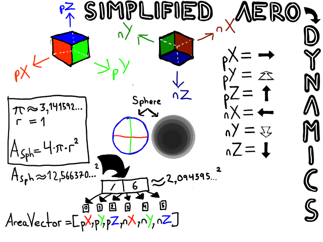
Alas, but I’m getting way ahead of myself. I shall go find an old drawing, here:

Edit:

You’re welcome! :slight_smile: Hmmm, this is true angular drag is difficult, perhaps because it cannot be adequately simplified? With linear drag, the forces are, well, linear - with angular drag, the forces are not aligned at all - hmmm, hmmm how can one simplify this mechanic?

This is interesting : D I’m looking forward to the update! :slight_smile: I’ll try to create a BGE version of my script, that way your aerodynamics may become easier for people to implement, instead of adding so many variables for surface area, the script could start with an init section containing something like this:

if(x,y,z,-x,-y,-z not in own.getPropertyNames()):
        calculateAreaVector()

This way, once the game starts the shape of the object will directly correlate with the area values : D

Attachments


I will read it when I get more time, but can you tell me how do I calculate the drag coefficient of object?

If I remember correctly, the drag coefficient is very difficult to calculate in a simple manner. The drag coefficient is usually discovered through testing in wind tunnels, or through advanced particle simulations. That being said, there are some good approximations for various shapes and forms here: https://en.wikipedia.org/wiki/Drag_coefficient

Can somebody make an advanced script(e.g. that uses particle systems or wind tunnel principals) that can calculate it? I need it by myself in Worn Tires to detect precise drag coefficient. And, to gain area more accurately, I should capture object in desired view(e.g. the one with Numpad 1) in orthographic view with transparent background. And than I must somehow find a program which tells how much percent is transparent. And than I take image size in worldspace(in meters) and calculate it’s area and multiply by transparency factor(e.g. if transparency is 40% than I multiply by 0.6((100-40)/100)…

Hmmmm… My understanding is that drag coefficient, is determined by fluid/gas flowing across an object, relative to its heading.
It follows then that the direction of that flow is important. If you put a plane in a wind-tunnel, you determine the drag coefficient by facing the plane towards the flow - because that most closely mimics the forces the plane will experience in the air.

However, as we’re planning on simulating a simplified version of aerodynamics, we can’t always guarantee the heading of the plane, so we must calculate the drag coefficient from at least six directions (x,y,z,-x,-y,-z).

If we do this, we can interpolate between these values, depending on the heading and orientation.

Now, as for the script itself, the process is almost identical to the one in my previous script.
Using the bpy module we can either pre-calculate the values, or we can go through the bge and calculate them from there.

Edit: After further consideration, there is a small problem, the drag coefficient is apparently only determined by the wing section of the plane. Hmmm…
Maybe one could vertex paint the wings a specific colour, and then have the script calculate only for those faces?

No… I need air friction for all the axis. It’s all. I can do rest myself. Just give me a demo that can find out the Cd by throwing particles at object. Than just rotate the object and run script, rotate again by 90, run script etc…

I need air friction for all the axis.

Isn’t that exactly what John_tgh talked about?

Edit: After further consideration, there is a small problem, the drag coefficient is apparently only determined by the wing section of the plane. Hmmm…
Maybe one could vertex paint the wings a specific colour, and then have the script calculate only for those faces?

Isn’t lift coefficient what depends mainly on the wings? And that only as an approximation because it’s the significant part because it was designed as such. Else the body is no less important. Which leads to the one-wing/only-wing plane.

Doesn’t the drag even depend on the integral of all discrete (simplified) cross section slices of the object?

Hmmmm… My understanding is that drag coefficient, is determined by fluid/gas flowing across an object, relative to its heading.
It follows then that the direction of that flow is important. If you put a plane in a wind-tunnel, you determine the drag coefficient by facing the plane towards the flow - because that most closely mimics the forces the plane will experience in the air.

However, as we’re planning on simulating a simplified version of aerodynamics, we can’t always guarantee the heading of the plane, so we must calculate the drag coefficient from at least six directions (x,y,z,-x,-y,-z).

If we do this, we can interpolate between these values, depending on the heading and orientation.

Not sure if this works, because even small variations in shape and surface properties can have huge impact, id est (=: i.e.) by reaching turbulent flow (often tied to a high Reynolds number, i.e. dominant pressure drag).

The here listed code is about object velocities far greater than wind speed the direction of the fluid furthermore stays equal for most of the time (until driver exempli gratia (=: e.g.) loses control and object heading differs from velocity direction),
therefore most of the time the simplified (constant) drag coefficient (=: c_d) may be used,
because Reynolds number usually varies little, especially in almost constant speed of the object, as does Mach number (which relates object velocity =: v to speed of sound in medium =: c, e.g. in fluid, e.g. in air at sea level =: 0m where often 15°C can be found => c = approximately 340.3m/s), the c_d may be considered constant.

Source: Clancy, L. J.: Aerodynamics. Sections 4.15 and 5.4

Anyway, calculating the values via particle simulation sounds promising and sufficient for each object for each axis direction and every necessary snapshots inbetween
depending on the object features,

e.g. for a 2d-rectangle-like object base (a flat car may be simplified to a ground-parallel plane) that’d be:
every corner of the plane / 2 (halved due to 1-axis-symmetry) + every side of its face + to right + to left + forward + backward = 8.

e.g. for a 3d-box-like object that might be:
#direction c_d snapshots = every edge’s most off-object pointing normal vector - 2 - 2 (minus due to the 1-axis-symmetry which renders two edges particle experiment’s theoretical results occurring identically twice) + every face’s normal - 1 (minus due to the 1-axis-symmetry which renders top left and right directions equal)
<=> #direction c_d snapshots = every edge’s most off-object pointing normal vector - 4 + every face’s normal - 1
<=> #direction c_d snapshots = 8 - 2 + 6 - 1
<=> #direction c_d snapshots = 6 + 5
<=> #direction c_d snapshots = 11

On every object deformation or surface roughness modification the c_d snapshots (cache) may need be updated.
Are there message topic posters and subcribers coded or planned? Keep it up.

@faerietree: I’m not sure I perfectly understand your entire post, it’s been a while since I’ve seriously studied physics, and aerodynamics for that matter - but, I’m getting closer :smiley: Check this out! This one runs directly in the BGE : )

There’s lots more to do still, and to understand. But it’s a start : D

Attachments

Windtunnel_Test_01.blend (978 KB)

I hate to be that guy, but finite-element analysis software already exists for this purpose.

An in-house implementation would be cool, certainly, but is it not a little premature to perform such analysis without planning to implement a finite-element tire simulation with laser-scanned world geometry to complement it? The accuracy of the numbers will mean nothing otherwise.

Maybe try finding the 2D area of the object’s silhouette along each axis? It’s an excellent approximation of drag for convex objects, and is occasionally completely accurate. Just render it and count pixels.

The drag equation has a constant for axis CdA which consists of:
Cd - drag coefficient (depends on shape, it’s fluidness)
A - shapes area in the axis.

I am aware of the drag equation. I mention the silhouette area because the algorithms presented so far don’t seem to form a basis around it.

The drag coefficient is what you’re trying to find with the wind/water/fluid tunnel. For a generic simulation, this means running the tunnel with every shape at multiple angles, at multiple speeds, in multiple fluid densities, with multiple skin drag coefficients. But even then, the results change drastically when other objects are nearby. And the tunnel had better simulate fluid cavitation. (Good luck convincing the average game developer this is time well spent.)

At some point realtime physics is about deception, not realism. With current hardware, a pragmatic developer will decompose concave objects into convex elements, make an educated guess at Cd and design objects so interpolated values are reasonable, add ground and slipstream effects, and walk away with a perfect deception and no time or money spent on finite-element analysis.

I dunno. An automatic wind/water tunnel sounds very interesting, particularly if it were built into the engine, but is it useful for this library? I don’t think many bge developers will want to bother with the complexity. Personally, I would have it automatically find the frontal area on each axis, then allow artistic control over Cd on each axis.

In games and basic simulations we don’t calculate drag coefficient runtime. Instead we have a constant precalculated. Here is an example of a lot of pre-calculated constants: Wikipedia Cd list For other manipulations we can use the density value(for example, in racing game you may reduce density when drafting).