Hi!
I am trying to achieve an “Ackerman steering” (See image) which is quite unlike what I can find in tutorials and on blendswap, but whatever I try I get cyclic dependencies and bones pointing every which way. Does anyone have an idea of how I should tackle this? Where should I put the control, what would be smartest to control, how would I link everything in the best way (and so on)?

Yep I do, but… I am too worn out now after a long days gliding, so I will give you some pointers tomorrow. The long and short of it is to use IK chains and correct bone geometry, I will post you a blend file some time tomorrow, after a much needed good nights sleep.
Cheers, Clock
OK - Ackermann Steering. The first bit to understand is the geometry of the setup. I think you got your image from here:
If not, then please read all of this page - particularly the bit that shows the steering arm geometry arrangement. you will notice that the two steering arms that connect to the cross link meet exactly in the centre of the rear axle - this is important and is the basis for making the rig. What I do is to draw the wheels and the bearings for the front suspension - this gives the rotational centre of the front units. Then place an empty at the centre of the back axle. Next create two bones that run from each steering bearing to the new empty - then scale them down so they are the correct length for your steering rack - the length of the bones is not important since the Ackermann principle is not conditional on the length of the link. So far so good - it’s picture time:
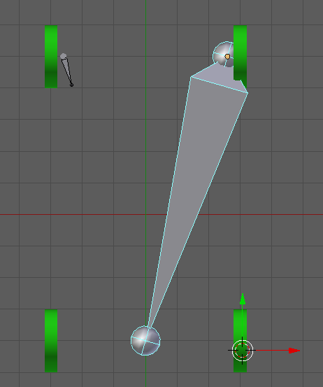
This shows the basic geometry with the left link scaled and the right one its original size.
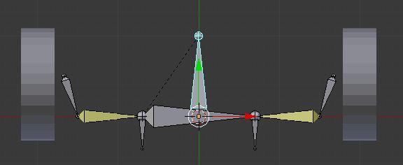
Next we create the new bones shown below:

The bone “cross-link” is parented to “link.L” , “link-IK.R” is parented to “link.R” and “link.R” is parented to “control” and must inherit rotation. Then add an IK constraint to “cross-link” with “link-IK.R” as the target and a chain length of 2 - this chain length is important if you want to make the rig more complex and have suspension, etc. Now when you rotate the control bone your steering works as it should. Then parent the meshes to the armature “With Empty Groups” and assign all vertices in the front wheels to either “link.L” or “link.R” depending on which side the wheel is of course.
Here’s the blend file to play with:
steering.blend (553 KB)
If you want to rig the typical setup where the steering rack is fixed, let me know and I can add this to the blend file.
Cheers, Clock.
PS. You might like to put a “Limit Rotation” Constraint on the “control” bone to prevent it over-rotating.
I wrote a thank you here, but it must have disappeared. Thanks! I’m getting closer to understanding mechanical rigging.
What do you mean by “the typical setup” by the way?
I tried what you showed me, and could use some further guidance.
In ackerman_ver2.blend (465 KB), I have made an alternative steering. I would like to control this by rotating the control bone (rather than what I have now, position in X-axis of the control bone), and have the ‘middle’ bone follow this rotation, but only with “lateral” (global X, local Y) movement.
This, I think, is a desired control since neither of the two wheels give the “correct” steering, so I thought I’d instead use a average value from a control of the middle bone.
I can see from your image that you have got it right! The only little thing is that you could have used the tail of your centre cross-link bone as an IK target fro the left track-rod bone, but that’s being picky…
You can also operate this kind of rig by simply sliding the centre cross-link bone in X as well as they way you have done it.
What I meant by “Typical Setup” is what you have modelled where the centre section of the steering rack is fixed to the car and the inboard ends of the track rods are effectively pushed left or right by it.
Cheers, Clock.