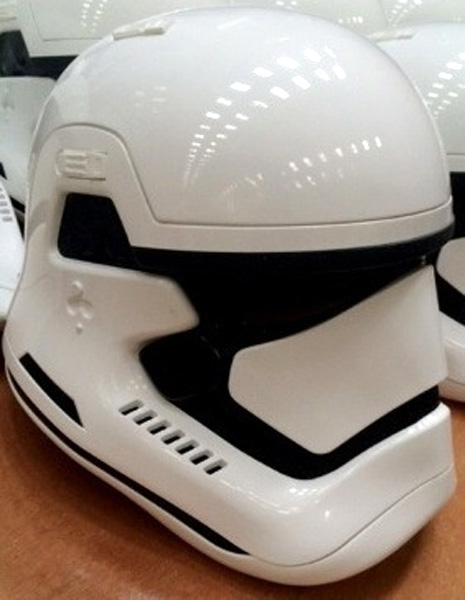
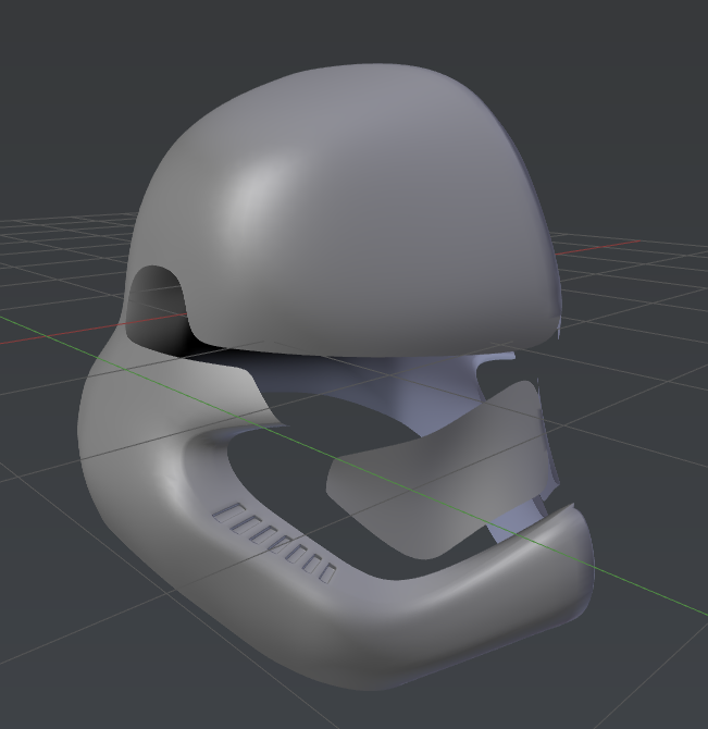
I have been working on this helmet(with the help of this wonderful blender community), and after modeling the basic shape now I want to work on details, the ones in the picture below. But I am stumped. I have looked online but haven’t found anything particularly helpful for my model. I have tried sculpting, but I failed at that. I just need to be pointed in the right direction. I feel kind of guilty for pestering you guys about this, but I really want my first model to look good. Thanks! Hopefully I won’t need any more help after this.
Your off to a good start, but before you go any further, remove the sub-surf and solidify modifiers. Now take a good look at your base mesh and work on cleaning up issues that will make the detail modeling much more difficult.
A. look for and remove any tris or Ngons
B. make sure the quads you end up with are all co-planer ( a fancy way of saying that each face is “flat”
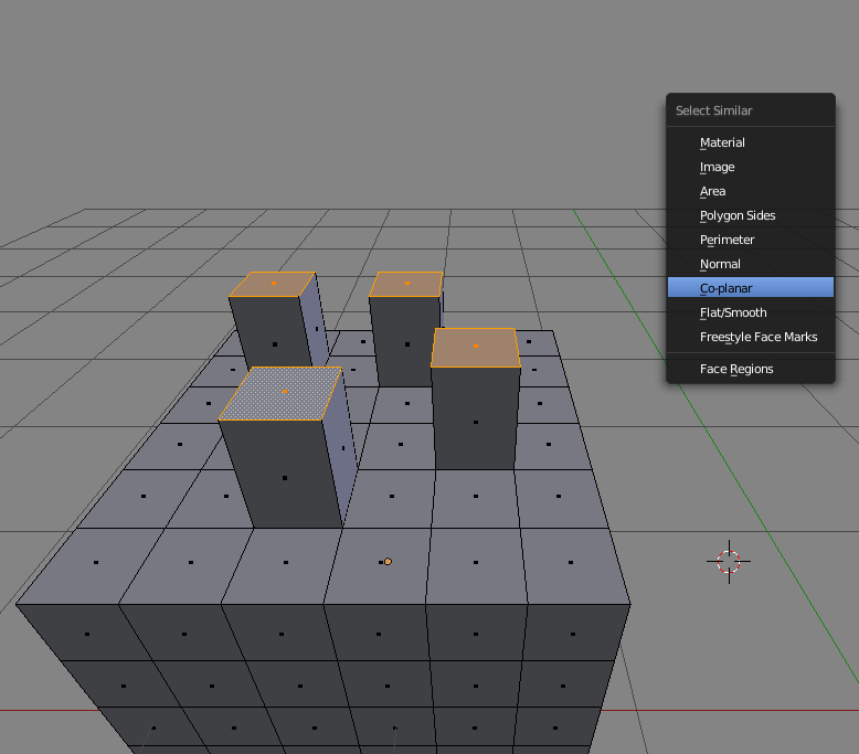
C. try to make the topology of the quads “flow” in such a way that you naturally can place edge loops to define the seams or grooves that go around the helmet - in the screenshot I have quickly done this with the Knife tool. In the process of doing so, more tris and ngons have been created that will have to be cleaned up.
So in essence with this modeling method you loop through a process of…
Create clean, simple mesh that defines the primary form made from all co-planer quads
Cut / Extrude /Inset additional details into the base mesh - bigger details first (hard edges / seams / etc.)
Repair topological issues introduced by the added detail
Repeat the last two steps until finished
Don’t get wrapped up in using as few quads as possible, focus on using just enough in the right places instead.
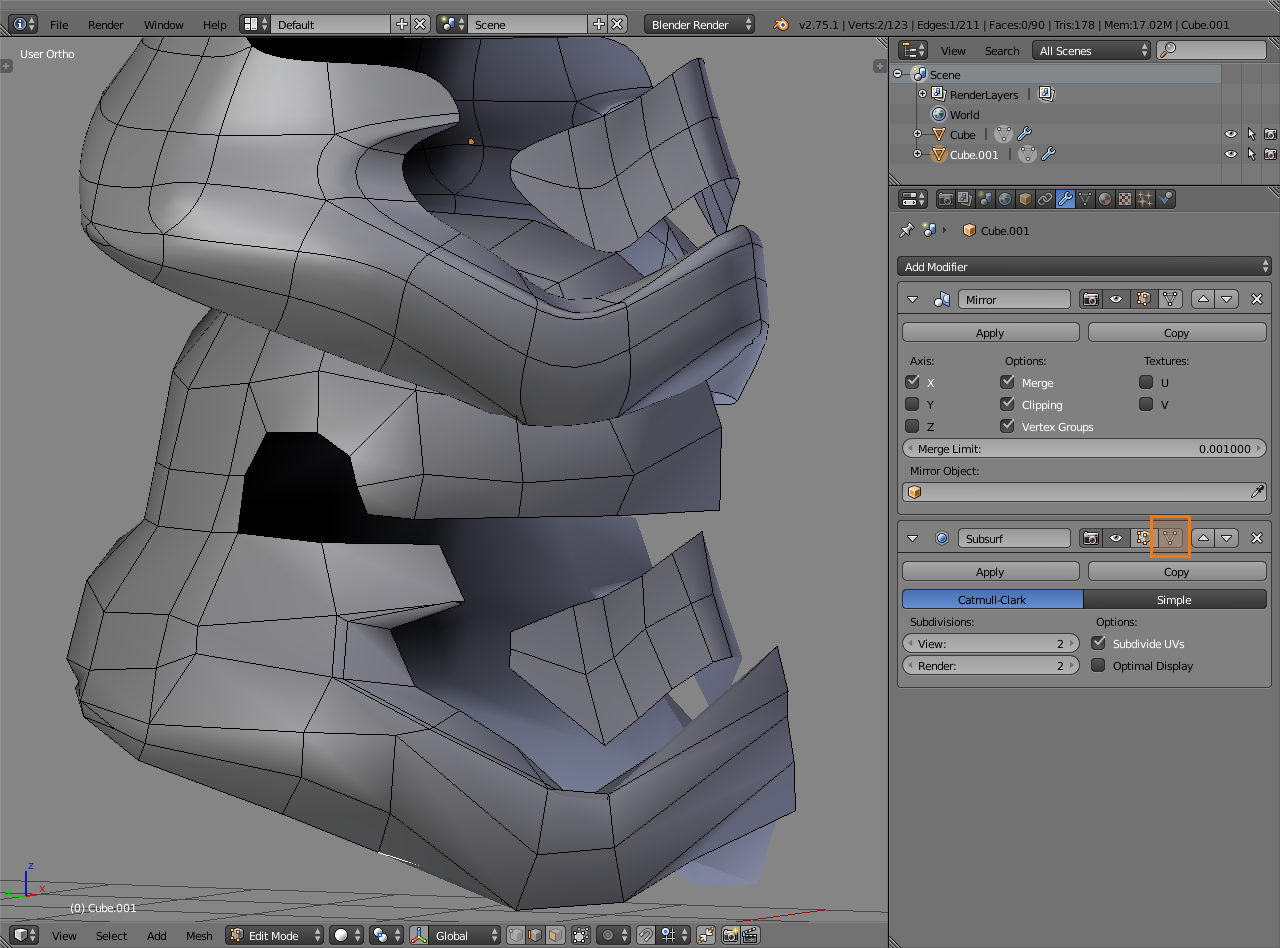
Your goal is to get the mesh looking “correct” to you without sub-surf at each level of detail, and then make it smooth for rendering with sub-surf - it’s fine to toggle sub-surf off and on to see where you need to add additional edges to control the surface and edge hardness, but I don’t recommend editing with it on as you will end up with non-planer faces like you currently have.
I reccomend you try to get the basic issues cleaned up and then repost your model
They don’t have to be absolutely flat, just close. Here’s why and one example of a problem non-planar quads might cause.
You have enabled subdivision modifier visibility on the editing cage itself which is very likely reason yours has severely non-planar quads and a bit of a mess
When you build your model, you are approximating curves and surfaces. Subdivision surface approximates new geometry based on that. If you enable modifier visibility on the editing cage itself, you’re not looking at true vertex positions but approximated positions and can end up with a mess.
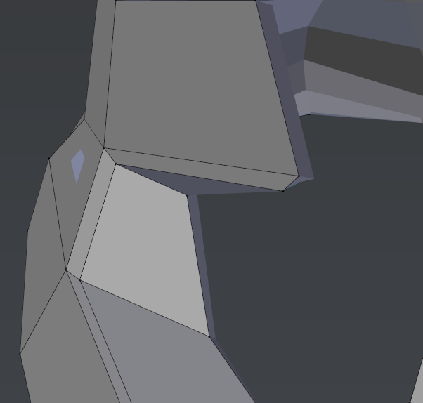
The subdivided result might look like it’s alright (top) but it’s not:
one face at the front has three of its vertices locked on the mirror plane,
one on the side is folded without having an actual edge on it,
and many of the vertices and edges are moved out of alignment which makes it harder to continue building helmet form and adding details, all while having face sizes transition gradually for smooth surfaces
You can drop subdivision level to 2. Won’t be needing level 3 in the viewport and probably won’t need that for rendering either. Use smooth shading to have it look smooth without ridiculous amount of geometry.
Ok,thanks. I have removed all the tris and ngons. But how can I make nonplanar quads planar? Should I just select points on a quad and try to flatten them?
Renzatic
(Professor Emeritus Billy H. Wafflesmith XIV Esq.)
5
Nothing so complex. Don’t worry about it being perfectly even. Rather, grab a vert or two on some of your more messy areas, and move them into position so your topology is smooth and logical. Your verts being a little more messy than they should be is what’s causing your solidify modifier to give you strange results.
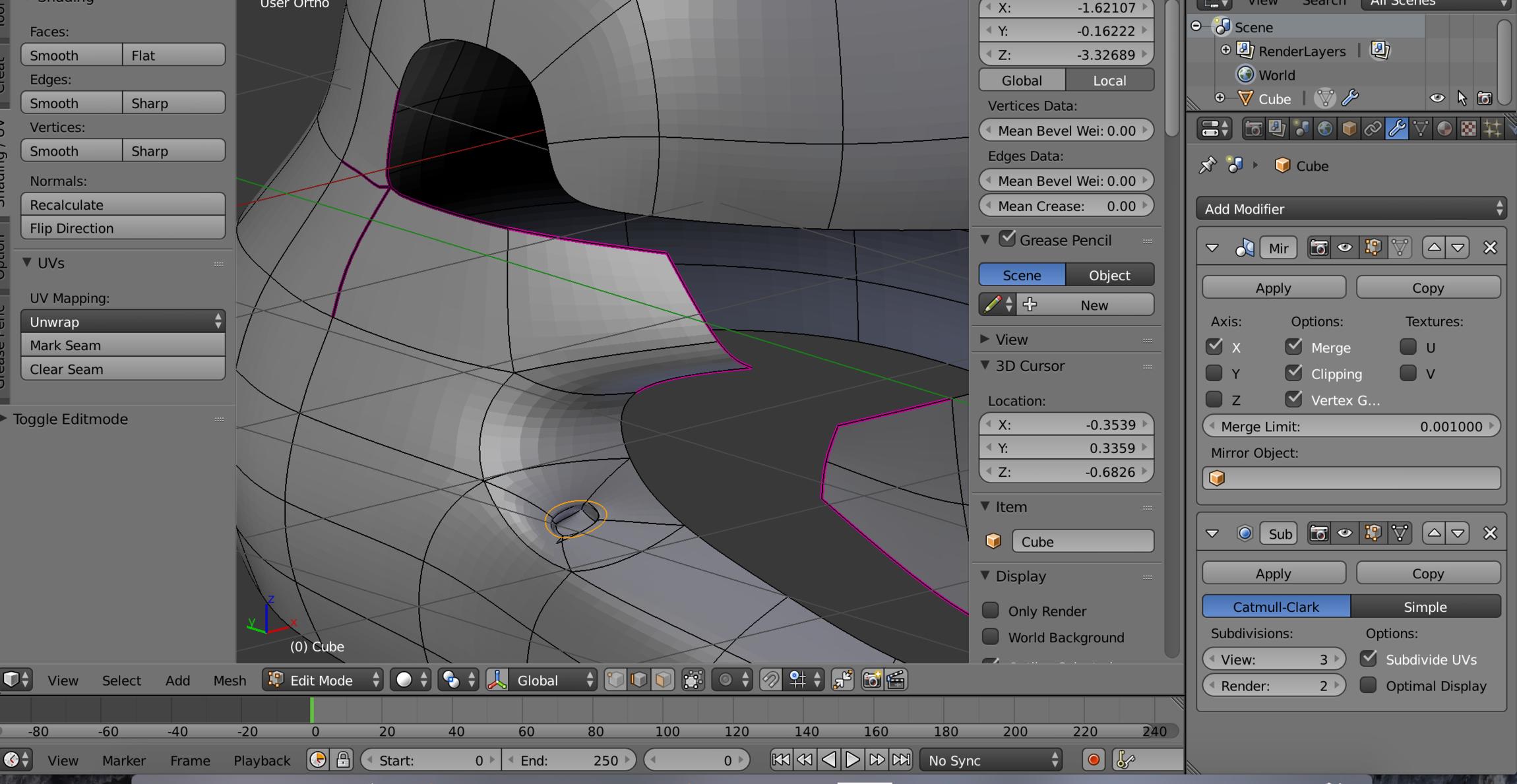
Ok, I am trying to make this edge straight, like in the picture with all the details, so I selected these edges and increased the mean crease. But nothing happened except it turning purple. So if thats not working, how else can I make it more straight?
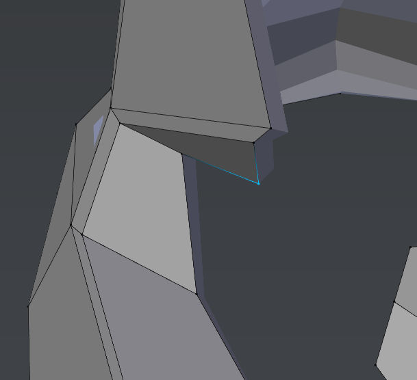
So, that worked for me, except in one spot. You can see where I extrude inward, it is of course an oval. I have not had any luck in making it rectangular.
The only problem with using the inset method is that it creates monopoles that can add pinches and, er…nipples along curved surfaces.
Though hen it comes to smaller details like this, it’s sometimes better to apply your subdivision surface modifier so you’ll have more geometry to work with. Adding in all the extra loop cuts and constraints required to model the groves like in your example above can mess up your base topology, requiring more work on your part to bang it back into it’s initial, smoother shape.
Once you’re happy with the basic shape, and want to start working on the finer parts of the model, thats the time for MOAR GEO!
Renzatic
(Professor Emeritus Billy H. Wafflesmith XIV Esq.)
12
Oh. CTRL+R. They’re bog standard edge loops.
While you’re at it, it probably wouldn’t hurt to look up a tutorial or two on subdivision surface modeling. Being able to predict how your subsurfs act will go a long way towards making you a better modeler.
Ok, thanks for all your help, but I am still having problems. Here is my updated file, and I have started to extrude near the bottom the helmet. but It is really messy, and I am afraid to go further. Any suggestions?
Renzatic
(Professor Emeritus Billy H. Wafflesmith XIV Esq.)
15
Yeah, that’s pretty sloppy. I’d stay away from insets in this situation.
Do what I said before, and apply your subsurf. But first, clean up your geometry so that the areas that’ll host your grooves are roughly equally square.
Then, drop into object mode, and head over to the modifiers tab. You’ll only want to get as much detail as you need. For my example, I set it to two.
Do this only when you’re happy with your base mesh, and are ready to start detailing it a little more finely. Applying the subsurf adds more geometry, which means it’ll make it that much more difficult to edit your overall shape later.
Then apply your edge constraints. What I did here was make a loop cut directly down the center of each groove, ALT-SHIFT-RMB clicked all my new cuts, then hit CTRL-B to run the edge beveler and adjusted it into place.
Then I hit CTRL-R to activate the edge cut tool, and ran an edge down the top and bottommost edges to maintain the rectangular shape when I reapply a subsurf modifier.
Let me reiterate that you should apply the initial subsurf modifier only when you’re happy with your basic shape. You have more geometry to work in finer details with, but it also requires you to select more verts, edges, and faces to adjust broader areas.