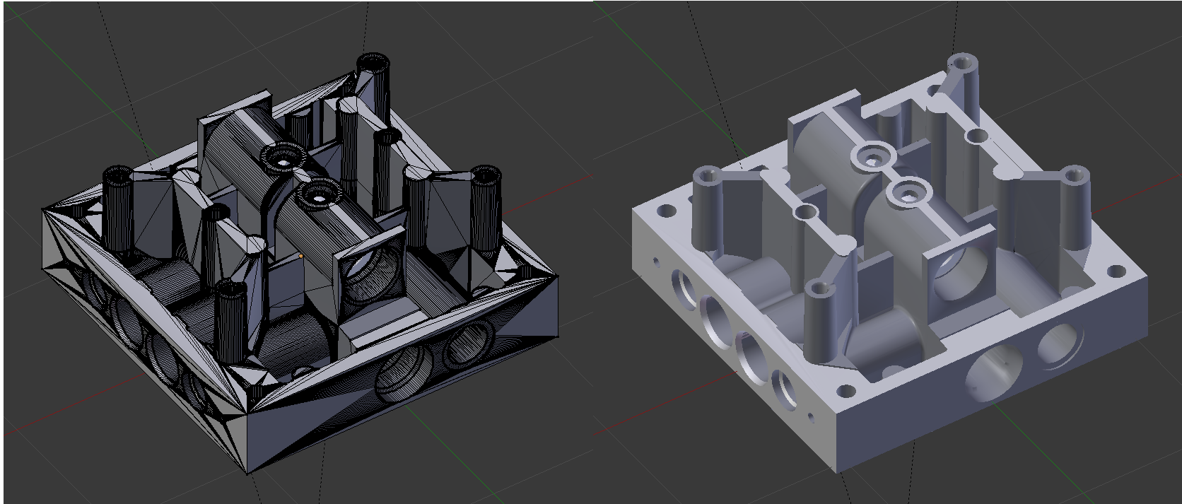
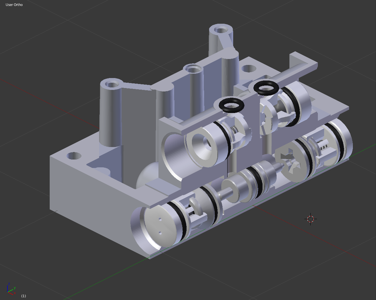
I’m finding myself in big trouble in trying to model the shape here below. I need this to animate a functioning sequence of an hydraulic circuit for training purposes. The image you see is the result of importing an OBJ exported from our CAD, but the drawbacks of this approach clearly appeared when I tried to render the image: odd shading, due to the high presence of triangles, and lot of un-needed geometry (it has just less than 32k vertices…). Using the edge split and decimate modifiers led to unsatisfactory results.
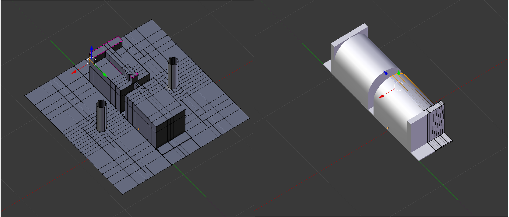
As far as the two side “sails” are concerned, I found a compromise starting from the central circle and extruding the various “separators” joining the outer circles and filling the resulting faces. I then joined this geometry with a bare resized cube underneath, to which I added some loop cuts before, with the hope of getting better results when using booleans to “carve” the holes in the lower part, afterwards.
The hardest part now is to model the central upper part. I couldn’t find any decent approach as to what to start from. I first tried to model starting from a plane (the aim was to be able to extrude the plan part down without having to join with the above mentioned mesh), but had to abandon as I couldn’t get the hemi-cylinder shape when arrived at the point shown in the left part of the image, then tried a cylinder that I cut in half (+ mirror modifier) and extruded down, but I always end up in not being able to create the two circular oring seats on top.
since you already have the cad model, the easiest, and quickest would be to do a retopo by hand. just add a plane to your scene, enable edit, enable snap to face, and move the points to the geometry. now extrude more edges and let them always snap to the surface. do it by logical parts, and it will give nice and light mesh then will render perfectly, and is easy to animate…
Ricky, it is totally symmetrical as far as the general shape is concerned. The holes are not, but I’ll take care of them once the overall shape is defined. I was already using the bi-mirroring (even though not for the whole shape) in the last attempt at modeling the center upper part (se the right portion of the last image), but thanks for the suggestion!
Ah, Max, you really have brain teaser here. I would first extrude the circle in the X direction maybe 24 points, then extrude it. Put your 3D cursor where you want the circle facing the z direction, the add the circle. Tune the size and verts in tool section of the UI, that way you can match up the topology.
Plus I would first start by running the limited dissolve on the edges as well. Cleans things up really quick. You may still get some artifacts, but the object will be much lighter to work with.
Thank you all for the answers and the lavished help.
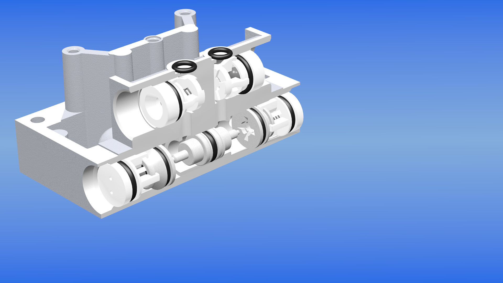
I solved the problem but I really don’t know how. Have a look at the two images: I noticed from the beginning that the reason of the wrong shading were mostly due to the mixed geometry (triangles vs quads, see the image).
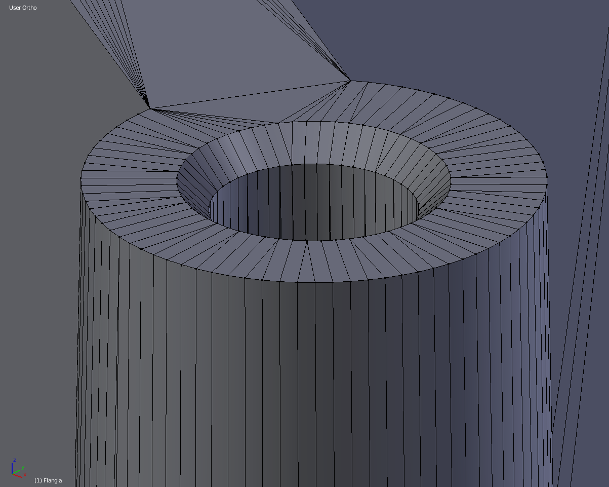
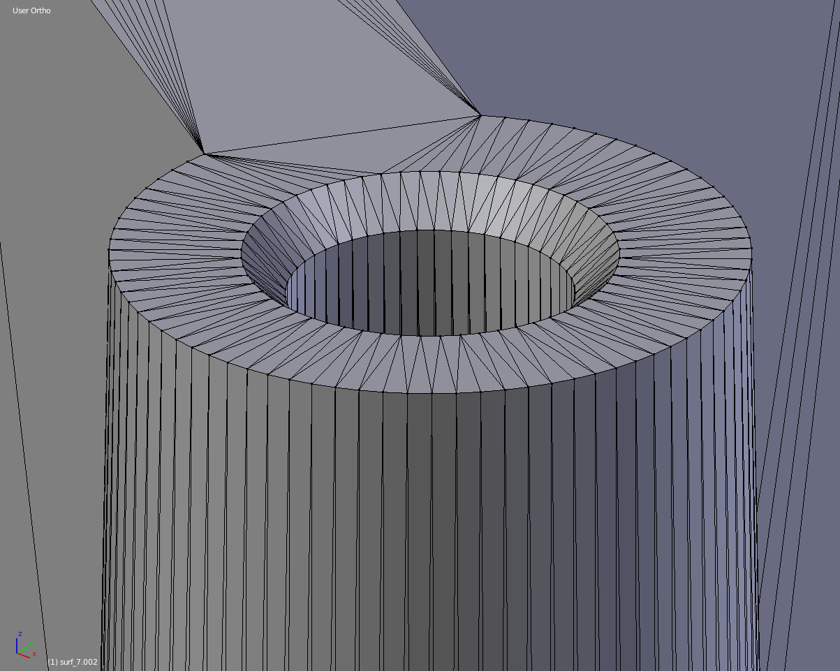
I tried to create a separate file in order to work on a revisited version of the flange in search of a more polished geometry (I found I was at a good point and I will for sure continue in the future) and containing just the flange without all the other internal valves etc.
I once rendered by error the imported mesh instead of the one I created and I suddenly noticed that it was redering perfectly. After inspecting the imported mesh, I noticed that it was made of just triangles. I can’t explain how this happened, as 1) the original file I imported is the same OBJ I imported at the beginning and 2) I re-imported the very same OBJ into the “complete” file and it was all triangles (and renders OK).
Now, as I don’t have a need to apply subsurf and I need to concentrate much more on the animation rather than the modelling, I call myself satisfied and I will continue modelling all of the other items while keeping the bigger one as is, but still I can’t understand what changed. As a side note (I think it is due to the fact that it is all tris, but I’m not 100% sure), it appears I can’t apply any bevel to the actual mesh: no matter what the values of the modifier are, it doesn’t change shape (I would’ve like not to have razor-sharp edges for a more realistic appearance).
for the internal part I think it should be separate mesh for animation with drivers!
now for shading problems you might have to add an overall edgesplit modifier
or control with the mesh autosmooth and play with angle to get nicer render !
Yes, the internals are all separated meshes due to the fact that they will be animated one by one. internals are already modified with edge split and the appearance is good enough for my needs (quite close to the real counterpart, at least in my opinion and still remembering that I’m not in search of photorealism). I won’t be using cycles as the final result will be an animation, it would take too much time to render a frame and being that it will be a technical video, I don’t need all the bells and whistles that cycles is offering (before I finally solved the problem with the shading, I was willing to use flat colors and Freestyle, and I liked it anyway )


 )
)