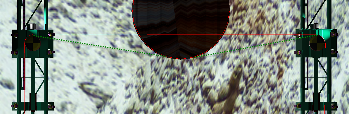
I am using bge.render.drawLine() to draw a wire around some circles in BGE. I got the straight-line (point to point) and the circle/arc around profiles down, but I’m trying to find a way to make the wire land on the perimeter of the circles as it should. This is to simulate a sort of rope/pulley system. Here’s what I have; I want the horizontal red line to follow the path of the green dashed line:
I want the red horizontal wire to deflect around the circumference of the lard red center circle. In order to do that I need to know the angle at which the left side circle shares a tangent with the center circle (an same for right). Any idea how to figure this out? I looked up the math involved and it seems pretty complicated; a compass would be needed in order to solve it on paper. But I’m hoping that since these aren’t actual circles, but 24 sided polygons, that this will be easier.Here is my current code:
import bgeimport mathcont = bge.logic.getCurrentController()obj = cont.ownersce = obj.sceneobjects = sce.objectsRGB = [0.0,1.0,0.0]GBR = [1.0,0.0,0.0]# Y is FWD/BACK (up & down the track)# X is left & right (port = neg, stbd = pos)# circles start from STBD side and go CCW#3-Dimensional cartesian distance formuladef getdist(Xa,Ya,Za,Xb,Yb,Zb): Xs = (Xa-Xb)**2 Ys = (Ya-Yb)**2 Zs = (Za-Zb)**2 return (math.sqrt(Xs+Ys+Zs))#generates the coordinates for a catenary/parabolic droop given 2 end points#Only in effect when the wire is slack; when tensioned, wire is straightdef create_catenary(amplitude,X1,Y1,Z1,X2,Y2,Z2,distance=0): #DIVIDE THE SPAN OF THE LENGTH OF PORT SIDE INTO 100 SEGMENTS #AND GENERATE A 100 SEGMENT LINE BETWEEN THE TWO POINTS if distance == 0: dist = getdist(X1,Y1,Z1,X2,Y2,Z2) else: dist = distance y_change = (Y2-Y1)/100 x_change = (X2-X1)/100 for i in range(1,101): deg1 = i * 1.78218 #180 degrees, divided by 101 segments deg2 = (i + 1) * 1.78218 Y = Y1 + (y_change * i) X = X1 + (x_change * i) Z = Z1 + (math.sin(math.radians(deg2)))*amplitude point_1 = [X,Y,Z] Y = Y1 + (y_change * i) - y_change X = X1 + (x_change * i) - x_change Z = Z1 + (math.sin(math.radians(deg1)))*amplitude point_2 = [X,Y,Z] bge.render.drawLine(point_1, point_2, GBR)flywheel_offset = .18X1_port, Y1_port, Z1_port = objects["PORT AFT FLY"].worldPositionX2_port, Y2_port, Z2_port = objects["PORT FWD FLY"].worldPositionX1_fwd, Y1_fwd, Z1_fwd = objects["PORT FWD FLY"].worldPositionX2_fwd, Y2_fwd, Z2_fwd = objects["STBD FWD FLY"].worldPositionX1_stbd, Y1_stbd, Z1_stbd = objects["STBD FWD FLY"].worldPositionX2_stbd, Y2_stbd, Z2_stbd = objects["STBD AFT FLY"].worldPositionX1_aft, Y1_aft, Z1_aft = objects["STBD AFT FLY"].worldPositionX2_aft, Y2_aft, Z2_aft = objects["PORT AFT FLY"].worldPosition#center circle/hemicirclestart_angle = 2 * math.piradius = 1.05#1.05sides = 24angle_increment = 2 * math.pi / sidescenter_x = objects["PYLON"].worldPosition.xcenter_y = objects["PYLON"].worldPosition.ycenter_z = Z1_fwdleading_edge_X = center_xleading_edge_Y = center_y - radiusleading_edge_Z = Z1_fwdend_angle = 1 * math.piwhile start_angle > end_angle: circ_x1 = round(radius*math.cos(start_angle) + center_x,2) circ_y1 = round(radius*math.sin(start_angle) + center_y,2) circ_x2 = round(radius*math.cos(start_angle-angle_increment) + center_x,2) circ_y2 = round(radius*math.sin(start_angle-angle_increment) + center_y,2) bge.render.drawLine([circ_x1,circ_y1,center_z],[circ_x2,circ_y2,center_z],GBR) start_angle -= angle_increment#port forward radius around sheave/pulleystart_angle = 1 * math.piradius = flywheel_offsetsides = 24angle_increment = 2 * math.pi / sidescenter_x = X1_fwdcenter_y = Y1_fwdcenter_z = Z1_fwdleading_edge_X = center_xleading_edge_Y = center_y - radiusleading_edge_Z = Z1_fwdend_angle = .5 * math.piwhile start_angle > end_angle: circ_x1 = round(radius*math.cos(start_angle) + center_x,2) circ_y1 = round(radius*math.sin(start_angle) + center_y,2) circ_x2 = round(radius*math.cos(start_angle-angle_increment) + center_x,2) circ_y2 = round(radius*math.sin(start_angle-angle_increment) + center_y,2) bge.render.drawLine([circ_x1,circ_y1,center_z],[circ_x2,circ_y2,center_z],GBR) start_angle -= angle_increment#correction for sheave/pulley radiusX1_port -=flywheel_offsetX2_port -=flywheel_offsetport_dist = getdist(X1_port,Y1_port,Z1_port,X2_port,Y2_port,Z2_port)Y1_fwd +=flywheel_offsetY2_fwd +=flywheel_offsetfwd_dist = getdist(X1_fwd,Y1_fwd,Z1_fwd,X2_fwd,Y2_fwd,Z2_fwd)X1_stbd +=flywheel_offsetX2_stbd +=flywheel_offsetstbd_dist = getdist(X1_stbd,Y1_stbd,Z1_stbd,X2_stbd,Y2_stbd,Z2_stbd)Y1_aft -=flywheel_offsetY2_aft -=flywheel_offsetaft_dist = getdist(X1_aft,Y1_aft,Z1_aft,X2_aft,Y2_aft,Z2_aft)#determine whether to slack wire or not# (if distance between pulleys is less than wire loop length)total_dist = port_dist +\ stbd_dist+\ fwd_dist+\ aft_dist+\ (flywheel_offset*4)print(total_dist)loop_length = 20.0790if total_dist < loop_length: amplitude = (total_dist - loop_length) * .5else: amplitude = 0print(amplitude)create_catenary(amplitude, X1_port, Y1_port, Z1_port, X2_port, Y2_port, Z2_port, port_dist)create_catenary(amplitude, X1_fwd, Y1_fwd, Z1_fwd, X2_fwd, Y2_fwd, Z2_fwd, fwd_dist)create_catenary(amplitude, X1_stbd, Y1_stbd, Z1_stbd, X2_stbd, Y2_stbd, Z2_stbd, stbd_dist)create_catenary(amplitude, X1_aft, Y1_aft, Z1_aft, X2_aft, Y2_aft, Z2_aft, aft_dist)
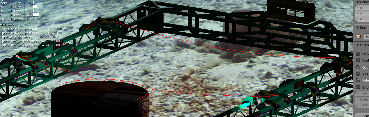
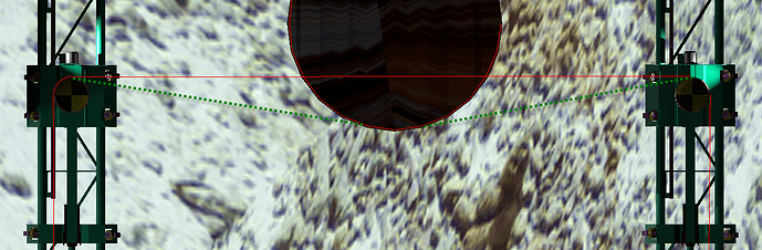
If you need some visual clarity on all that catenary stuff in my code, see the attachments.