AN-Drone-ID

Edit2:

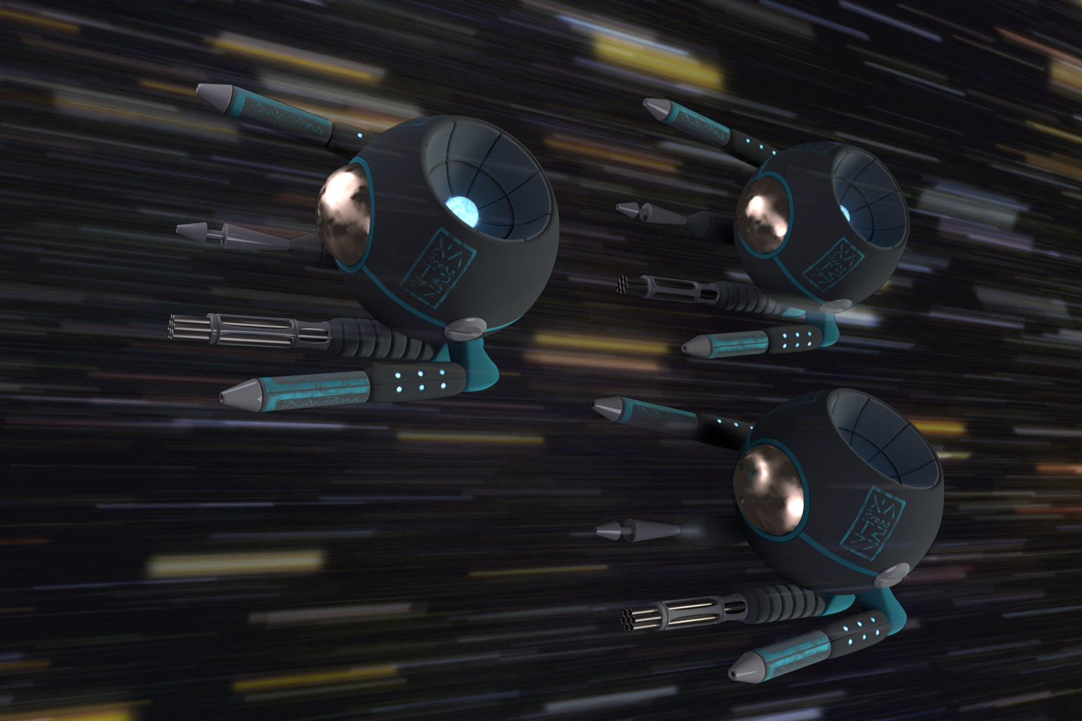
I made an image of the drone in situation using three drones and postworked a 2d background.


Edit:

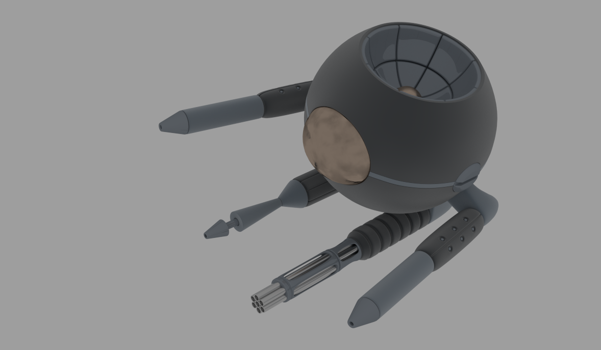
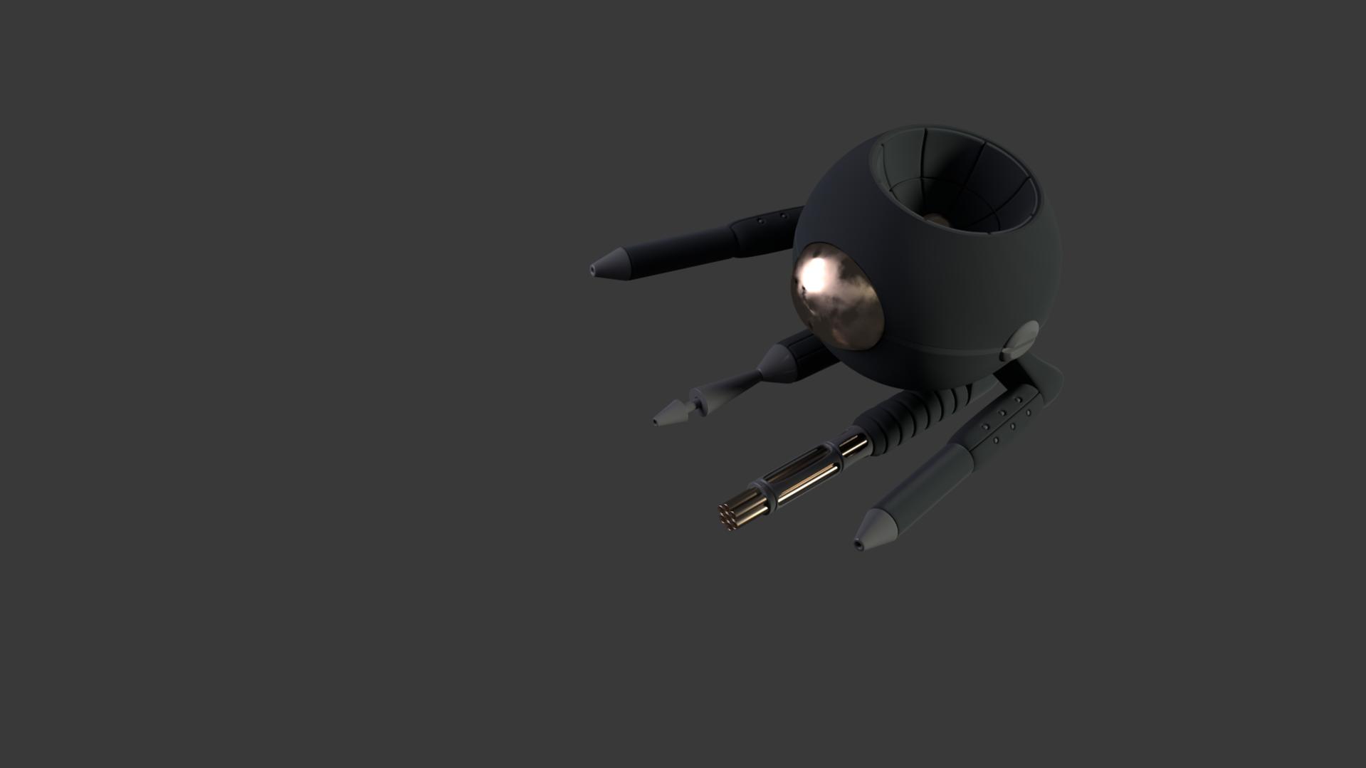
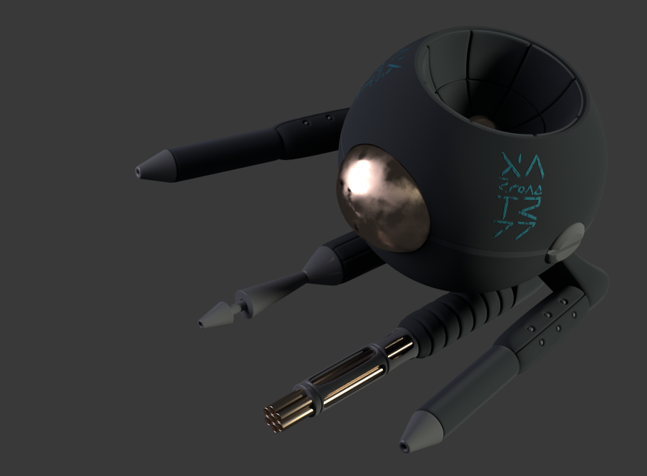
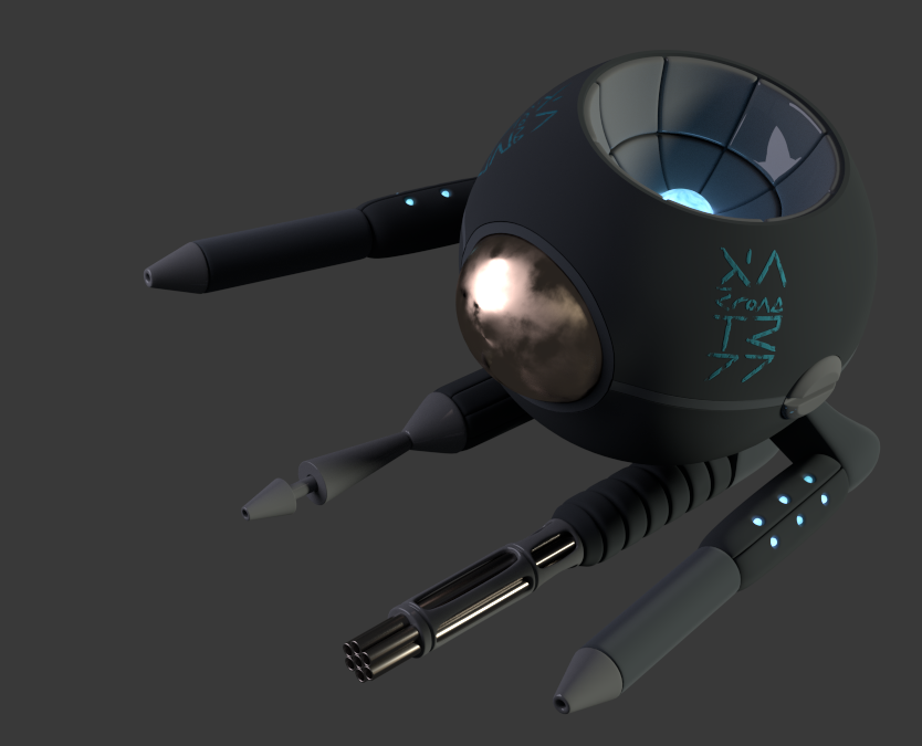
I started some material test. More glossy than expected, its only some procedural home made or CC-0 from blendswap. I plan to go further probably ading some vinyl usung some Si-Fi elvens wrighting I made years ago or maybe new ones but I try to get the basics right first, thats the start of it.

I wanted some CC-0 HDRI as material are very sensible to light I guessed having a good one from the start will save me work laster. The only thing looking like it was a render scene from blendswap named somthing HDRI or the contrary. I appended the scene in mine and … nothing apend aint some material in the material list so I guess I did it wrong.

[ATTACH=CONFIG]368062[/ATTACH]

The last .Blend
http://www.pasteall.org/blend/35095

Edit end

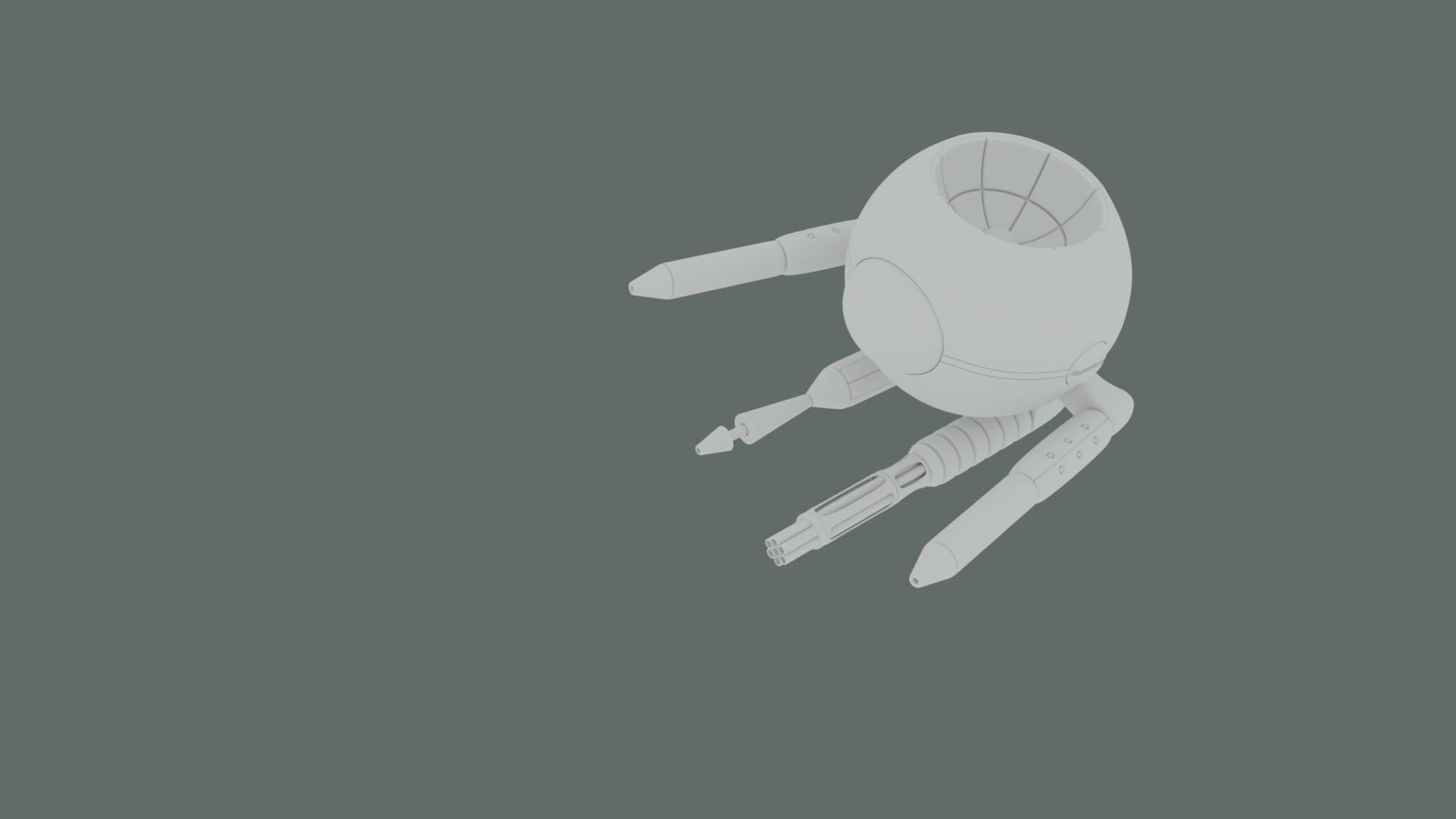
I have almost finished the modeling of a Si-Fi thingy based on an old drawing of mine.

I guess I’ close to texture it now. Yes I m afraid.

I guessed I’d better try to show it here before starting the texturing in the case I made something especialy stupid in the modeling part. As I dont model a lot and I restarted using blender some month ago after a very long pose, it may toatly be the case.

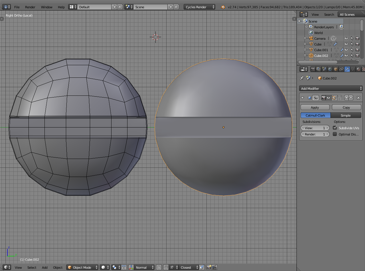
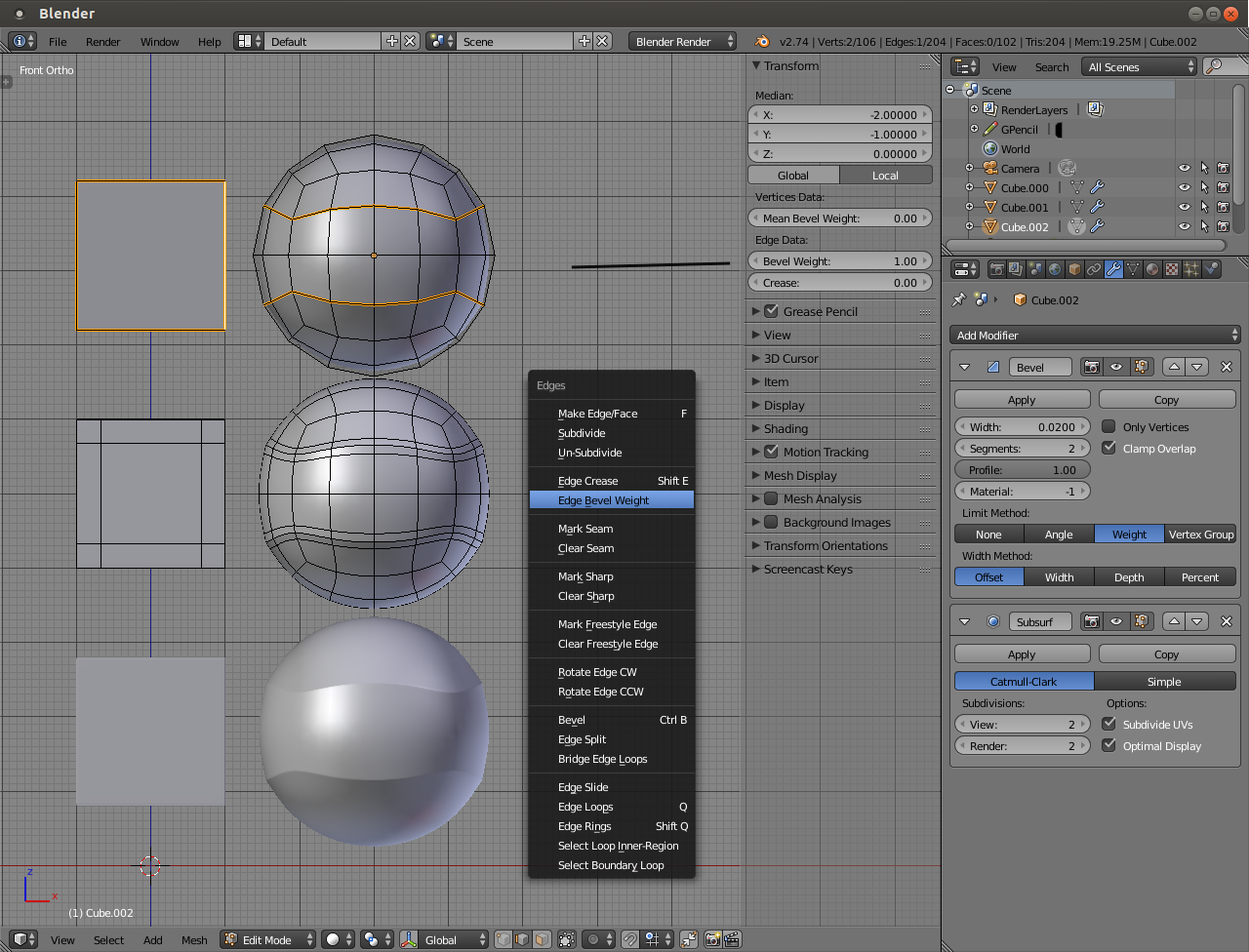
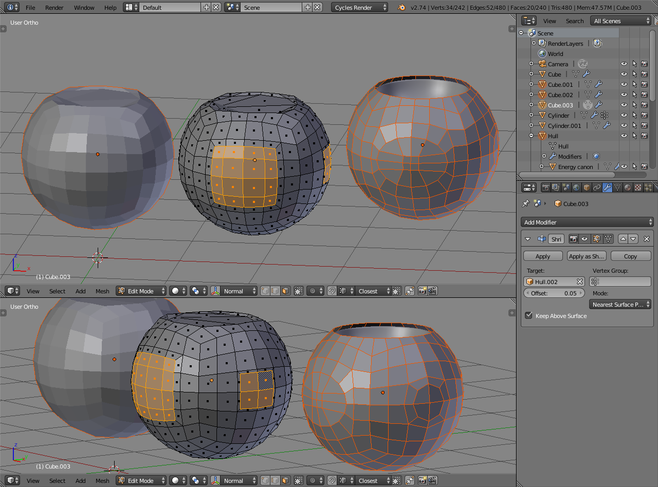
I’m not realy happy with the 6 dot plate part. I tryed to remodel it twice and it wasnent realy better nor realy worst by the way. I just dont have a clue how to have the dots without messing the roundness of the whole thing.

I’m not happy with the joints around the screw either. But as it dont look that bad on the clay render, aint somone come with an easy way to improve it, I probably let it like this.

I may add some joints at the junction betwine the main body and the “arms” of the drone, but as I modeled it with a view angle to shoot it in mind, and that we dont see these part on that angle, I may end up just been my lazy self.

I’m planing of using mostly not glossy texture as glossy is not a good idea for a combat drone in my opinion, aint probably on the bubble glass part that I will try to get an old mirror glass look if I figure out how to do it. Maybe the metal part of the gatling may have some too but I probably will want dull metall here so not a lot of glossy I hope there too. So I guess if it looks decent in clay render, it will go well once textured too. I obviously reserve my jugement on the materials as I may change my mind in the process. Glossy and non glossy ceramic may end up on some parts as well as ceramic make sens if I go for air-space drone. Not sure though.
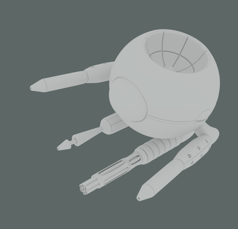
Clay
[ATTACH=CONFIG]367656[/ATTACH]
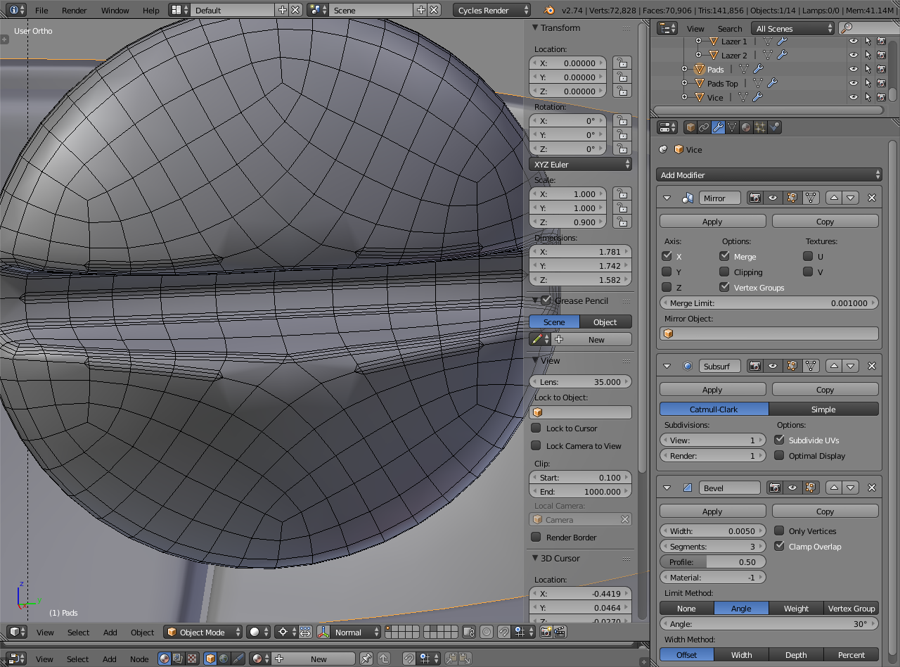
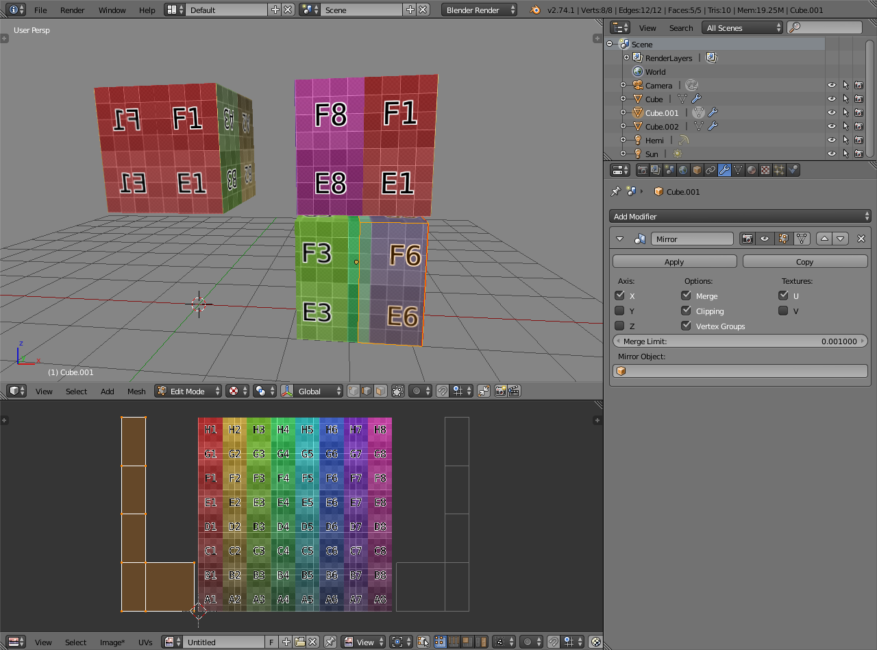
Wire

[ATTACH=CONFIG]367657[/ATTACH]

Attachments


Good that you included the .blend because the wireframe without solid faces is nearly always useless, can’t see the important bits because it’s just many layers of crossing lines.

The model didn’t look bad. Noticed couple of things though


Modifiers shown are for the object in the viewport. Viewport properties are for the selected object (named “Pads”).

The modifier order matters, they get applied from top down. Bevel works on the subdivided result and it’s limited by angle. In this case it doesn’t give good results, it only bevels some of the edges.

Some of the objects have non-uniform scale which is visible on the 3D view properties. That will mess with tools and modifiers, and with UV unwrapping later on if left unapplied. Ctrl+A -> scale to apply.

Angle limit with bevel modifier doesn’t give a lot of control. Assigning bevel weight (ctrl+E -> bevel weight, or 3D view properties) for edges gives more control and if you want to use the bevel modifier to control the subdivision sharpness, could set the bevel modifier to do 2 segments and set the profile to 1. It puts control loops on each side of marked edges.


Or you could control it manually

I also modeled couple of pieces again since you mentioned that you’re not happy with them. Maybe they work as another take on what their structure could be. Air_Space_Drone_alpha8_ja12.blend (363 KB)

Thx, I will try to understand all this.

I could’ve been more clear about the bevel weight. It was late.


Here I’ve changed edge bevel weights to 1 on all cube edges and some on the polysphere. That is used on bevel modifier to control which edges are beveled. I’ve set segments to 2 and profile to 1 so it creates control loops on each side of those marked edges. When the bevel is above the subdivision surface modifier, those get added before subdivision so it controls how sharp the edges are.

Sorry I wasnent implying you werent clear enough.

I generaly to try to watch the work of others in this section of the forum and in other places before I try to make some myself. I didnt had blender open and I wanted to thx you but planed to anderstand all this in an hour or two.

I guess some extra explaination is a pretty good ending to this missinterpretation, at last on my side of things.

I was self-critiquing my own output. I made a tutorial (linked in my signature) about asking questions more clearly so that kind of means I should be more clear with the answers, especially whenever there’s a .blend available.

But yea, check what works for you and if something is unclear about the explanations, just ask.

Ok I just opended your .blend and your remodeling of the two part I strugled with are far bettter than the original ones.

I anderstand how you did the canon doted pading part I think. I will have more trouble reproducing what you did on the hull padings.

I think you started with a subdivided cube and a spher and retopoed the cube on it? If so I have no real clue how as I have seen a not of retopo tutorial with diferent technics but never passed to practice so it all melted together in my head mainly. What specific technic did you use? I guess there is already tutorials about this somwere but If its prety simple to explain, it will same me time as I will have to find and watch a lot of them until I found one that explain what you did and I may miss that its the one technic you use even then. If it isent simple to explain, I will look it up myself of course.

Edit: I think I anderstanded both when I realised I didnt anderstanded the canon pads part after I tryed to reproduce it. I may be wrong again thoug. Did you used a shrink modifier once you add the general mesh to get the individial vertex to be at the proper place?

Yes, exactly right.

I used W -> subdivide smooth on the default cube to add geometry, and to sphere (alt+shift+S, 1, enter) to make a polysphere. Then I used the existing hull and shrinkwrap modifier. Polysphere gives a better starting point for the cuts.


Top faces get squished since the hull is not fully round, but that’s ok, can scale the top vertices to 0 along Z and get them to snap on the hull edges. Inside faces of that are then deleted, creating the hole on top.

Used inset (i) tool for front and side, which I then rounded with looptools addon: circle function. You can also shape these manually - Scaling along Z to get the oval for the front and smoothing geometry around for both the front and sides. Shrinkwrap keeps the general ball shape.

That’s how I started it. You could cut and add the mirror modifier above the shrinkwrap and start making the cuts after that.

I did it rather quickly and it’s not perfect. The cuts don’t follow the hole roundness that well but with a bit of tweaking you could make it good enough. Starting with non-symmetrical circle for the holes might make it easier http://www.blenderartists.org/forum/showthread.php?300493-Symmetric-circular-cutout-with-subsurf-topology-problem
but should be fine with this approach too.

Ok, Thx.

I think I keep your version of the Pads and try that technic on the doted one that is better than mine but not exactly how I want it.

I dont realy see the point on redoing somthing you done as I would have liked to be able to do myself in the first place. Aint that if the final result is not to bad, I will probably upload it on blendswap under CC-0 so I better ask you if that’s ok with you that I keep your pads. If not I will try to do it myself.

Of course. They’re not perfect but if they help to get what you need, then by all means use them.

I remade the doted pads, they are more like I wanted them and now I think it may actualy look better due to the irregaluarity I wasent able to get rid off in the previouse version. I probably decide on that tomorow. It may not be that hard to grab the older version from a previouse save.

I added joint betwine the pads and the “arms”. Thx to let me use your version JA_12, it save me time. The joints arent very good but will do aint it’s on very close up I think.

I tryed to make the part of the arms that link with the hull a little better. The lower ones were two diferent object, non realy practical to modify them armoniously, so I made them one mirrored thing.

I’m tempted to add more joint lines on the pad but as they werent on my original sketch, so I not sure. maybe one in the lower part and one in the back will make sens and make the uv unwrap easier at the same time but I’m not sure I will do it.

I tryed the weigth option of the bevel modifier and its definitly better. I didnt change it on most of what was already done as it look mostly ok, I may revise my jugement if there is something look bad once I’m doing the materials.

I retopoed the screw a bit but I dont think it show a lot on the render.

I twicked the lazer.

I think everything had slight change aint the hull and glass now. Probably the next image will look mostly the same anyway. O_o

The blend.
http://www.pasteall.org/blend/35088

Attachments


I edited the first post with a new render.

I toyed shortly with the materials and light. Still a lot to do.


I’m trying to add some whorn ID on the drone.

I made a first test but as I’m using mirror modifier on everithing that is the same on both side the texture is mirrored too and the lettering is not in the good sens on the mirrored part. Is there a way to avoid this probleme or stop this part of the texture to be mirrored with the rest of the texture? I want to keep the modifiers as I may want to do some change on the model later.

Any other feedback will be welcome of course.


Yes, there is a textures U/V option on the mirror modifier. Enabling that mirrors the UV coordinates too so that they take their own space on the UV area, which results to unique areas being shown on the model

The cube is mirrored along X:


Default behaviour on the left. Textures U option enabled on the right. Had to drag the UV island off the UV area to show the UV’s themselves and that there are two islands instead of one overlapping another.

Thx, I’ll try this.

I put JA_12 explaination at use and my text is now mirroring the proper way.
Added an emiter material for the power core that I used on other part as well. It’s prety basic but I think it will do the tricks.
Added some geometry around the mirror glass and atributed the light grey velvety texture to it. I think it improve the look greatly.
Made some minor change on the material and geometry in the gattling.

I think I’m happy with the modeling now, aint some idea pops or I did somthing wrong that I missed.

I’m close to let my laziness win and call it finished, but I have one or too idea of texture to try before.

I’m not totaly sure of the light on the plasma canon, I let them here until I make up my mind.


The .blend ( The worn text texture is missing as I m not sure if I want to work it a bit more and have no clue how to remove it once its packed in the blend.)
http://www.pasteall.org/blend/35149

Great result! I like it!

If you want to go further in the texture of the main sphere, it could be interesting to vary a bit the roughness of the material so that differs a bit from one point to another to make it maybe a bit more realistic. This tuto from Gleb Alexandrov is great for this.
I did not tried this method yet in one of my project but I will.

I totaly like this guy tutorials on light I watched some of them. I take a look on this one and see if I want to use it on this model.

Thx.

Ok I just watched the tutorial and it’s a good one as all the one I’ve seen from creative shrimp. Sadly not a lot in it to learn for me. If you downloaded the .blend that were under the last version of the drone, there actualy is an anisotropy shader that use this technique here with procedural instead of an image map but the logic is the same.

I didn’t use this trick on the hull pading since I wanted it to contrast with the bubble mirror glass. I ear that you are thinking I made the bad choice there and you may be right. I had the idea that this will be the black OP version of the drone when I started the texturing proccess and that this velvety material will be at once more discreed that a glossy one and some kind of autoreparing futurist material. I probably missed the mark if it look wrong to you. I already derived a little from my initial plan of totaly dull and dark look I had in mine at start, adding more ceramic that I planed and the blue textvinile and the light, so I don’t mean it’s set in stone. Sadly I dont realy see how to use roughness to make this material more si-fiy and keep the contrast betwine smooth and rextured betwin the diferent materials. Not saying it isent the way to go but I have no idea how to.

I however already had some idea at using somthing around this technic to add some scratch on the glossy ceramic material I use on the tip of the canons and around the gatling and power core. I’m not sure I will succed since I never did it in cycles but some scratch and used part may be cool on the ceramic assuming I do it right. If I’m both not to lazy and had any succes with it, it may apend at some point.

I have to add some more vinyle before so it’s hard to make prediction right now. Plus next version of blender is suposed to add, if I anderstanded right, a new node that I’m realy eager to try. It may help get the scratch and worn mark on the edge of the geometry without having to use uv unwraping and dust image map, so I’m not in a hurry to do this part since I may have far more fun ( or headash) with this new node.