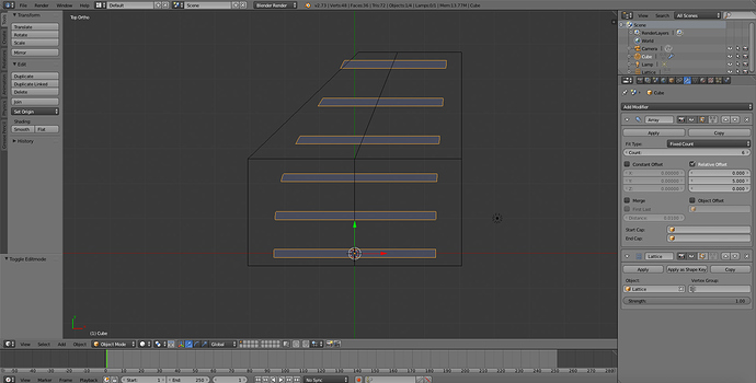
Curve stretch?

Picture if you will that you were trying to model something like sailfish spines:

(For a proper analogy to what I’m doing, picture that they’re all perfectly parallel)

Now, let’s say you’ve made one spine and you want to use it to create the whole array of spines. So you put an array modifier on it. Fine, but now they’re all the same length. It’d be lovely if we could create a curve to determine how long they are - the higher up the curve, the longer they are, and conversely, the lower on the curve the shorter they are.

But I can’t figure out how to do that.

I’ve figured out how to use curve deform to bend all of the “spines” in my work, and to offset where they start, or rotate them, or whatnot, but I can’t seem to find a way to use the curve to stretch them across one axis. Surely there’s some way to do it in Blender, probably some easy way… I just can’t find it.

Help? :slight_smile:

Add a lattice to the scene and scale it so the spines are in its boundaries.
Add a Lattice Modifier to the spine array, then select the lattice object in the Lattice Modifier.
Now start moving the verts of the lattice which will deform the spines…


one more… make sure in the stack the Array is above the Lattice Modifier.

Thanks! Unfortunately, I’ve encountered a new problem.

My “spines” aren’t perfectly straight; they have a bend to them. To be more specific, a “spine” is made of a straight solidified beveled bezier curve (just two endpoints in the curve, no bend), and I have separate “control” bezier curve which acts as a Curve Deform on them (I use a separate bezier curve rather than having the curve that makes up the spine bend in order that I can use the same “control” curve to deform multiple elements, not just the spines). So my modifiers without the lattice go Curve Deform -> Solidify -> Array, and I get a perfect array of evenly long curved “spines” (mind you, they’re not perfectly cylindrical as I’d like, as the Curve Deform makes them a bit elliptical when it changes their angle - but that’s not a show stopper).

That’s how things are as it stands. But when I apply Lattice that you recommend after Array, the severity of the curve changes. Where the spines are short, it becomes a sharp curve; where the spines are long it becomes a shallow, barely noticeable curve. What I really want is the curve to retain the same slope throughout - aka, if one spine starts off curving up at 15 degrees, then they all start curving up at 15 degrees; the longer spines just reach a greater height than the little ones. Is this possible?

Basically, when you think about it, what I really need is that the “spines” get scaled on all axes away from their starting point, not just length (so that the slope of the curve remains the same) with the caveat that the curve bevel that turns them from a curvy 1d line to a 3d object is done after said scaling (otherwise, a spine that’s say three times as long would be three times as thick, and that doesn’t work for me at all - I’m modeling something that’s going to be made out of constant diameter pipe). Can you think of a way to do this? Because the curve bevel that transforms it to 3d is part of the bezier curve object properties, not a modifier, so it always happens before one can apply any modifiers, which means it’ll get warped by any scaling :frowning:

I think another possibility to achieve the same thing would be if I did it like you describe, but that my Curve Deform modifier came after both the Array and Lattice modifiers. If it would deform each element in precisely the same manner and apply the same slope to each spine in the array regardless of the length, then that would be a pretty good approximation of what I need (The option described in the preceeding paragraph would be better, as it wouldn’t make them elliptical - but this would be good enough). Unfortunately, when I try moving my Curve Deform to after the Lattice modifier, it starts looking all weird - the first “spine” gets curved right, but all subsequent ones get weirder and weirder. It doesn’t at all apply the same curve to each element.

I hope that what I want to do is possible. :frowning:

Hmm… I don’t remember whether the lattice can scale on multiple axes (I don’t have access to Blender at the moment, and that was the first time I’ve used a lattice), but if I remember right it can. I was thinking, maybe I could apply the bevel in the curve properties for the “spine” that turn it from 1d to 3d be some finite but incredibly small value, and then have a solidify modifier without a cap and with a fixed thickness (the outer diameter) come after the Array and Lattice modifiers, and a second solidify modifier (with a cap) applied after that with a fixed thickness (the inner diameter). If I’m not mistaken that’d create something sort of like a coaxial cable, with the “spines” that I want at the proper diameter and thickness, with a second tiny pipe (that I don’t really want) on the inside. But if that inner pipe was so small to the point of invisibility, then one would only see the outer, desired pipe that makes up the spine (if I’m not mistaken!), right?

Maybe not ideal, but I think it might work…

Hey, that “coaxial cable” trick worked. And the only cost is a practically invisible “thread” on the inside (you also have to clamp the solidify). So cool! :slight_smile: If it bothered me I bet I could get rid of the “thread” with a decimate or something. But for now I can keep going with my project.

Oh, one more discovery: the default lattice interpolation type, Bspline, was causing all kinds of weirdness that I couldn’t figure out; if I aligned the lattice to the object then stretched it, the object wouldn’t stretch at the same speed as the lattice. Eventually I tried swapping it to Cardinal and it now behaves intuitively. Yeay! :slight_smile:

Hmm, and now I have an idea on how to do it even better which I’ll try this evening. Instead of making the “spines” 3d via solidify, I could potentially make a simple pipe object, just a little short slice, and then use an Array modifier set to follow path - the path being the arrayed, deformed “spine”. Maybe that would work? My only concerns would be the possibility that maybe it wouldn’t follow each arrayed copy, just the original. I guess I’ll find out.

If it does work that would help me with some other problems, I have one type of “spines” that aren’t circular profile, and I also need to panel over the area between them with regularly spaced objects (they can bend with the curve, but their size must not be stretched). If the Array-along-path will follow each of the deformed, arrayed paths, then I think it’ll do just that. And no more “coaxial cable” issue :slight_smile:

(In case anyone’s curious, what I’m actually working on is a design for a greenhouse to be built into the landscape over a ravine. The roof height and width are not constant, the ground is uneven, and the roof is halfway between a V and an arch, for greater strength against wind than a pure V but better ability to shed snow than a pure arch. The “spines” are the structural aluminum supports, of three different types - main supports, secondary supports, and the I-shaped glazing framing; there’s also horizontal supports and the polycarbonate glazing panels, which can bend slightly but come in fixed sizes. The whole thing is designed to be built flat on the ground and then fold into shape as it’s lifted off the ground. The model has to be flexible because first it’ll need to be tweaked after glazing material selection, then again after surveying is done, and then again after my engineer goes over it - hence my desire to use adjustable arrays and curves rather than just hard-coding mesh geometry.

Just in case anyone is actually reading this and was curious :slight_smile: I just figured that a sailfish spines analogy would be much easier to picture!)

Nope, total dead end. One has to use a curve modifier with the array fit to curve, and both just work on the raw curve, no modifiers taken into account. If I want several “spines” (poles), then I have to apply a second array modifier to the slice object, and then after that, the lattice deform. Which scales and warps the cross-section of the poles.

Ugh.

Okay, finally a solution that rather works, even if it is a bit complex. :slight_smile:

I create the components that get assembled into spines and such, and array them out as needed. I build a simple wireframe mesh whose shape is the area I want my model to exist in. The mesh’s edges are subdivided a few times. All of my components get mesh deform applied using that mesh, and bound. They also have a boolean intersect operator against the mesh, so that anything outside of the area gets clipped off. As for the deformation mesh, I use a couple of hooks to empties to warp it.

Why hooks to empties rather than just warping the deformation mesh by hand? Simple: because whenever you change something with the mesh or the object being deformed by it, you have to rebind to an undeformed version of the mesh. By having the deformations be in the form of disableable modifiers, they can be switched off relatively quickly for the rebind.

It’s not perfect (the rebinds are a little annoying), but it does the trick. :slight_smile: Note that one can’t use pure bevel-extruded curves with this approach, as you can’t boolean a curve. But you can have a curve, and then have an object Arrayed- and deformed- along the curve, and then mesh-deform and boolean that.

To prevent warping of my objects (such as the “spines” / supports becoming elliptical or changing in size), a simple rule is necessary: the deformation mesh must never change in width (because that would mean resize), and when it goes up or down, it must rotate its angle to match its direction (otherwise, that would make things elliptical).

So yep… not perfect, but it works. :slight_smile: