Ok I’m having to rewrite this because chrome crashed and I don’t know how to recover drafts. It keeps saying auto saved as I type but I have no idea where to find the save.
Ugh. I’m going to be hasty and direct with it this time.
I’m working on some game resources for a game I’m hopefully going to make and I’m currently modeling a rifle concept. The rifle has a roughly square body but then it has several curves transitioning from the body of the gun to the pistol grip.
I used to just eyeball curves like this by extruding flat surfaces and then manually placing the vertices along the curve by eye. But first, I don’t feel like this is good enough anymore, and second, I’m working from a hand drawn reference image so nothing is quite straight or quite smoothly curved anyway.
So how would I go about extruding consistently curved surfaces from a flat surface? I want to be able to make a perfectly consistent circular curve as I extrude instead of just eyeballing it. Also if I want a curve to be parabolic, to change the sharpness of the curve as it progresses, how would I make a curve like that, and/or extrude one from a flat surface.
Ideally I want to learn how to make any mathematically consistent curve quickly.
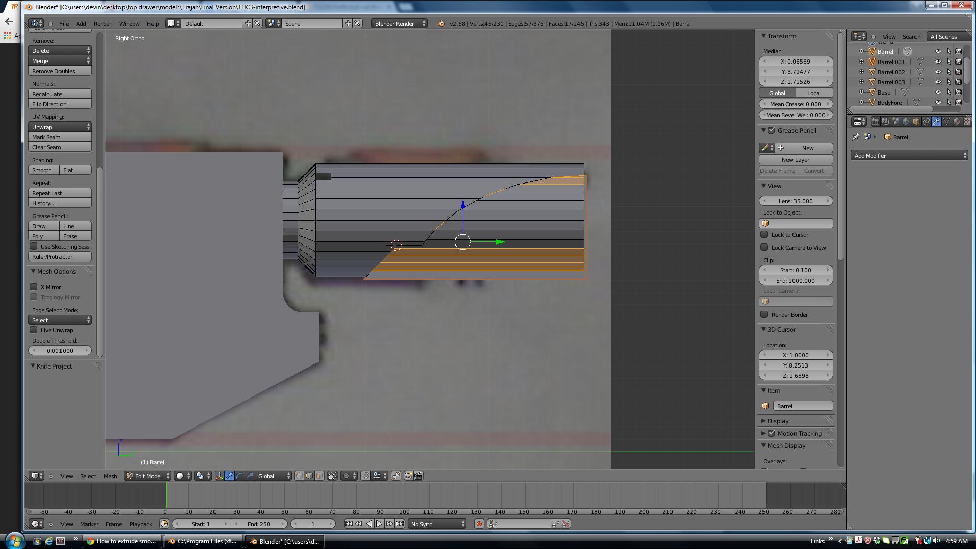
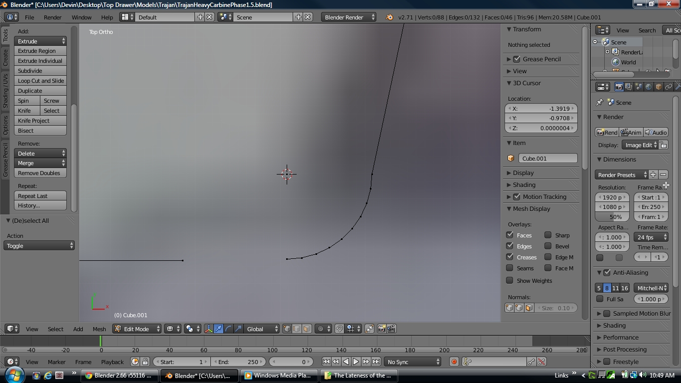
Right now I’m using my own improvised method of manually integrating circular curves into square bodies but it’s absurdly convoluted, time consuming and tedious. Here’s an example of how terrible it is.
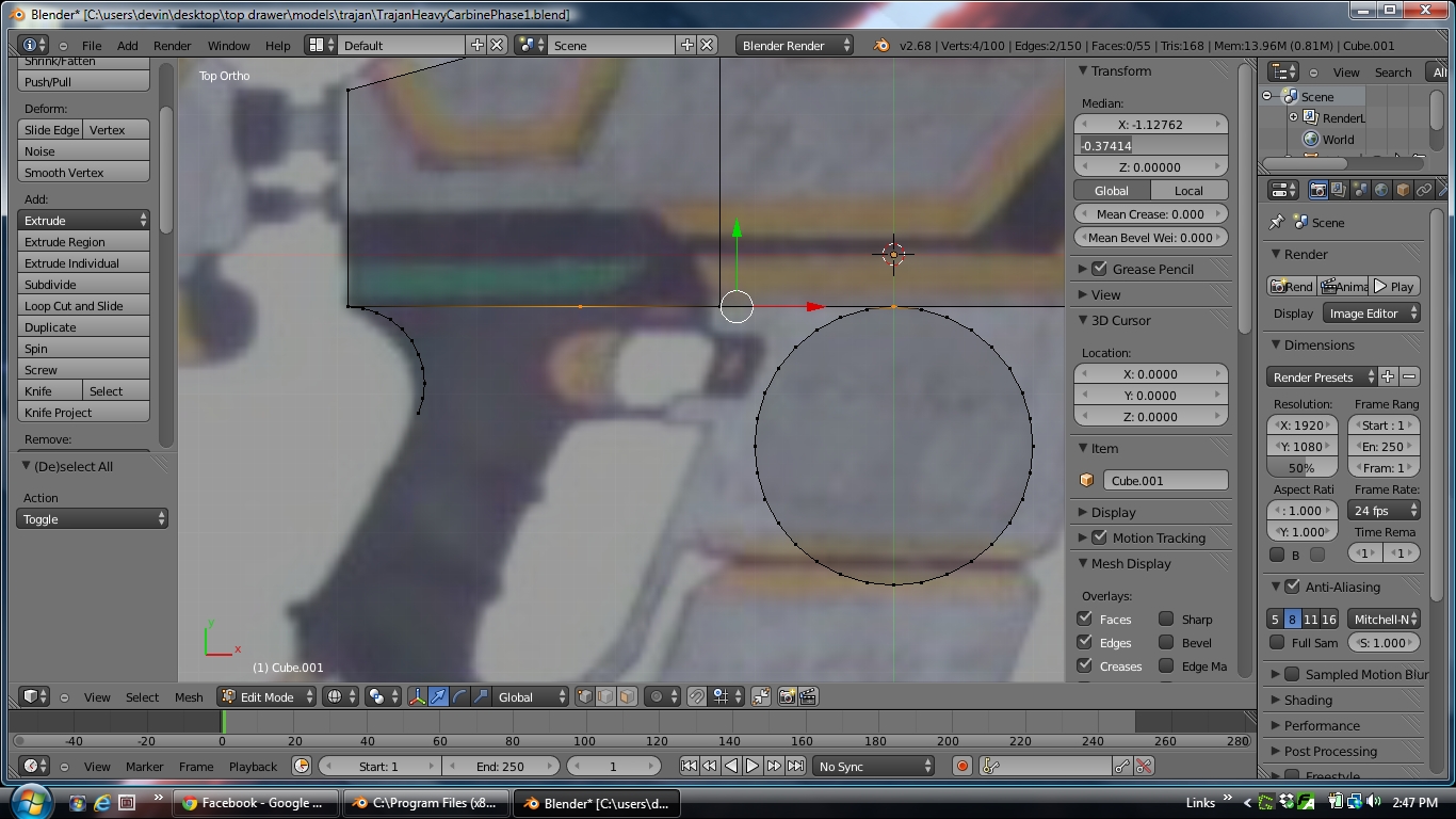
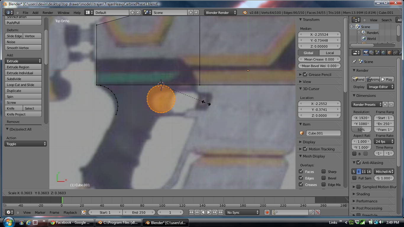
Here’s the model I’m currently working on. I want to make the curved inner surface of the trigger guard, but I don’t know how to make a perfectly smooth curve by extrusion. So I place a cylinder.
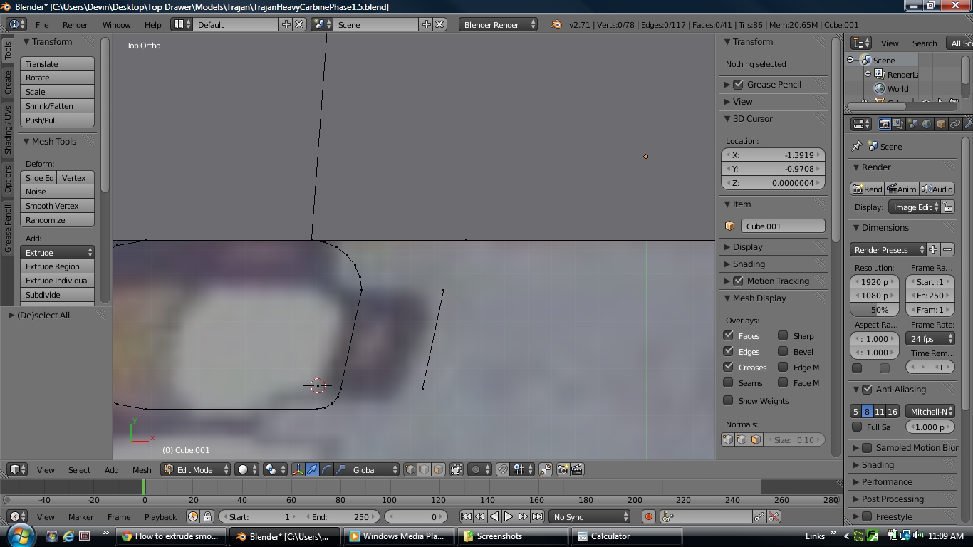
Then I manually measure the difference between the position of the vertices on the cylinder that I want to connect to the rest of the gun, and the target vertices I want them to attach to.
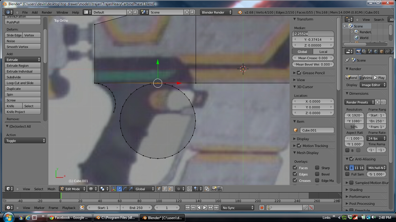
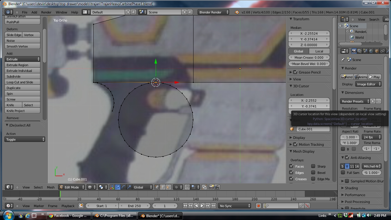
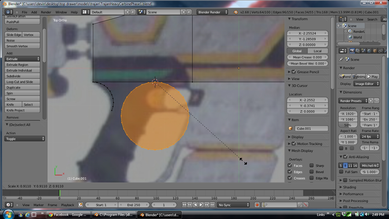
Then I align the 3D cursor with those vertices and set the pivot point to 3D cursor so I can scale the cylinder without misaligning the vertices I so painstakingly aligned.
Then I delete out all the vertices from the cylinder that I’m not going to be using, and lastly, I would manually “stitch” in a face on the sides by connected all of the vertices you can see in the both those curves on either end of the grip.
Do you see how insane that is? And then I would have to repeat the process over and over again for every single curved surface! the front of the trigger guard isn’t one curve, it’s two connecting the three sides top, bottom, and front, instead of 90* corners. So I’d have to do all of that again to make the front of the trigger guard. And this "stitching is the slowest and most painstaking part of all. I KNOW there’s a built in tool for making curves so I don’t have to do all of this. I just need someone to tell me what it is and how to use it!
Press SHIFT+D to duplicate it, then move it down (press the X/Y/Z axis letter to constraint the move) then enter/left click to validate
Select both vertices and press SHIFT+S -> Cursor to Selected
Select one of the 2 vertices only (in my example i’m using the bottom one) and click on the Spin button
Press F6 (or look in the Operator panel, bottom of the toolshelf to the left of the 3D View) and change the setting according to what you want , the amount of vertices created and the angle.
(Note : the vertices on the top aren’t automatically merged, you’ll then have to Select All , then W -> Remove doubles to do so , if you need of course)
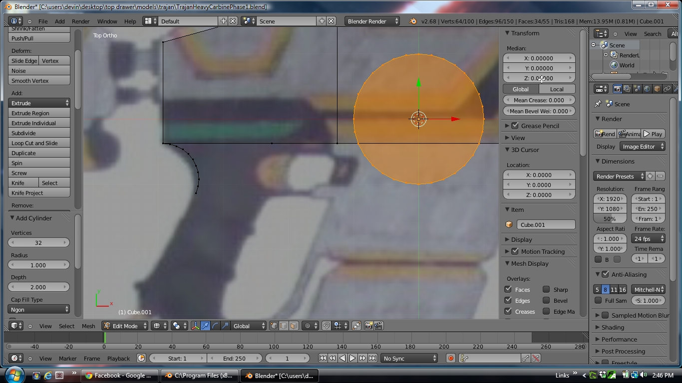
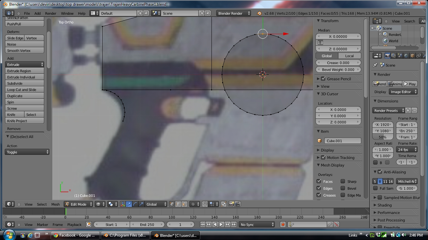
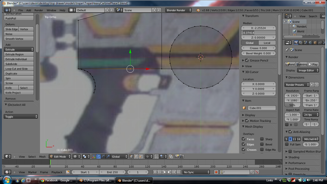
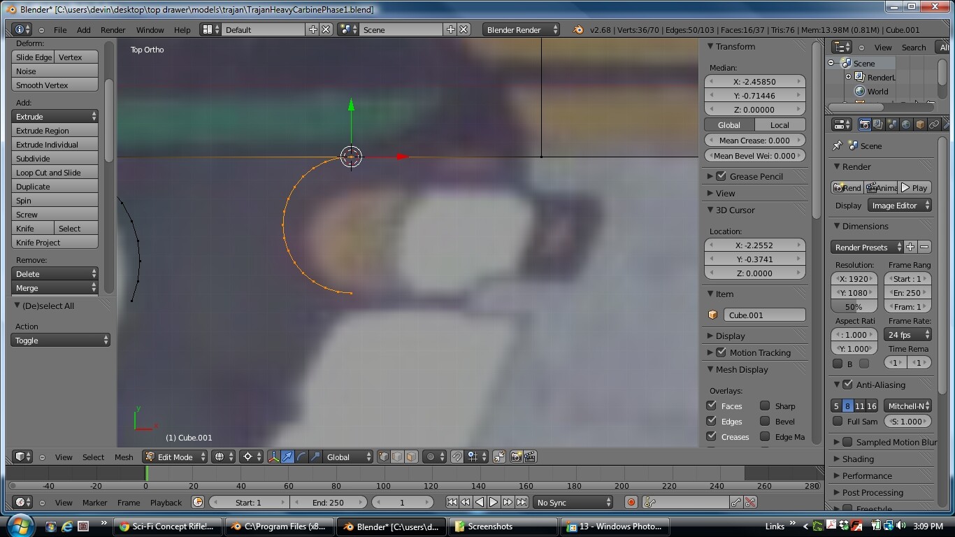
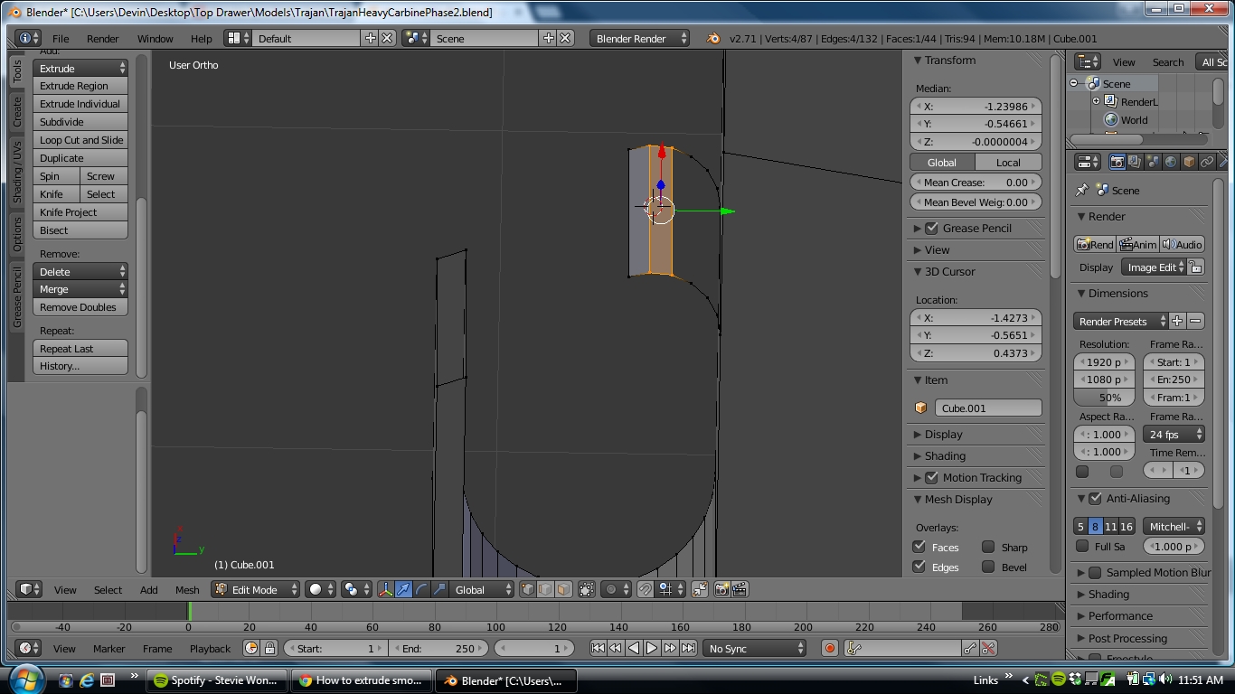
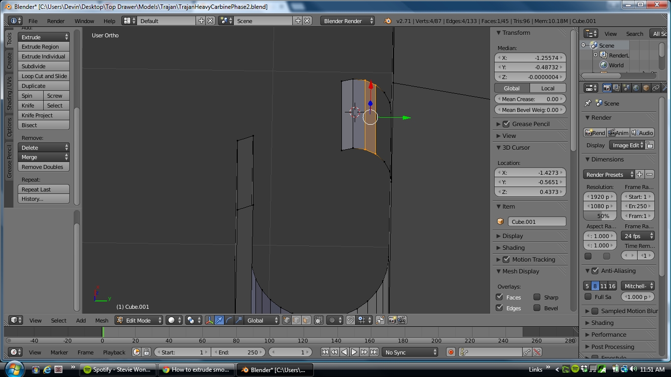
Ok so I’m learning to use the spin tool and I’ve run into another problem. I’m trying to form the curve at the bottom of the trigger guard. What I’ve done is places a vertex an equal distance from the front of the trigger guard and the bottom to serve as the axis to spin around. But placing the axis this way messes up the back swept angle of the front of the trigger guard. The pictures show what I mean by that. What I need is to spin axis from the front of the trigger guard down to the horizontal, but continuing from the current angle of the front piece. Again, the pictures will demonstrate better than I can explain it, what I need to do is place the 3D cursor higher but I have no idea how I can figure out exactly how high to place it to get the right angle on the spin.
Ugh! In which my alignment issues continue to abound! Now I want to form the outside of the trigger guard, and I want it to maintain the same angle as the inside so I’ve duplicated the forward face of the inside of the trigger guard to start from. I want to connect it to the bottom of the body of the rifle but I have no idea how to extend it up without changing the angle of it???
As you can see in the screen shot I improvised a solution to that problem I had with the bottom curve for the inside of the trigger guard but I’d still appreciate any input anyone has as to how I would place the 3D cursor for use with the Spin tool precisely in order to maintain an angle I’m spinning off of.
Thanks again for the help. I haven’t been working on it but I’m going to check out those extended tools sometime this week.
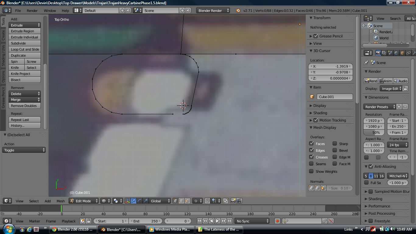
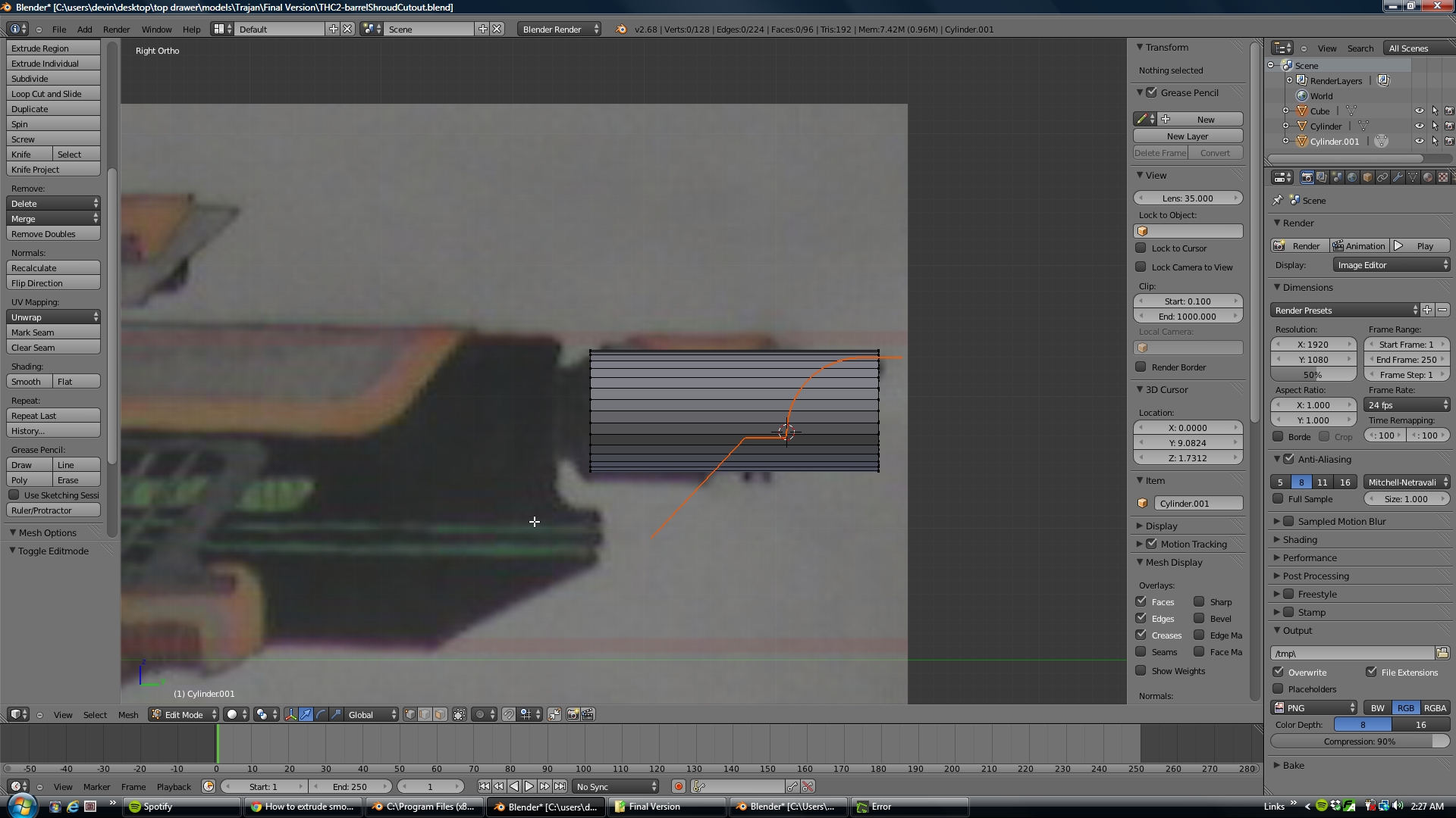
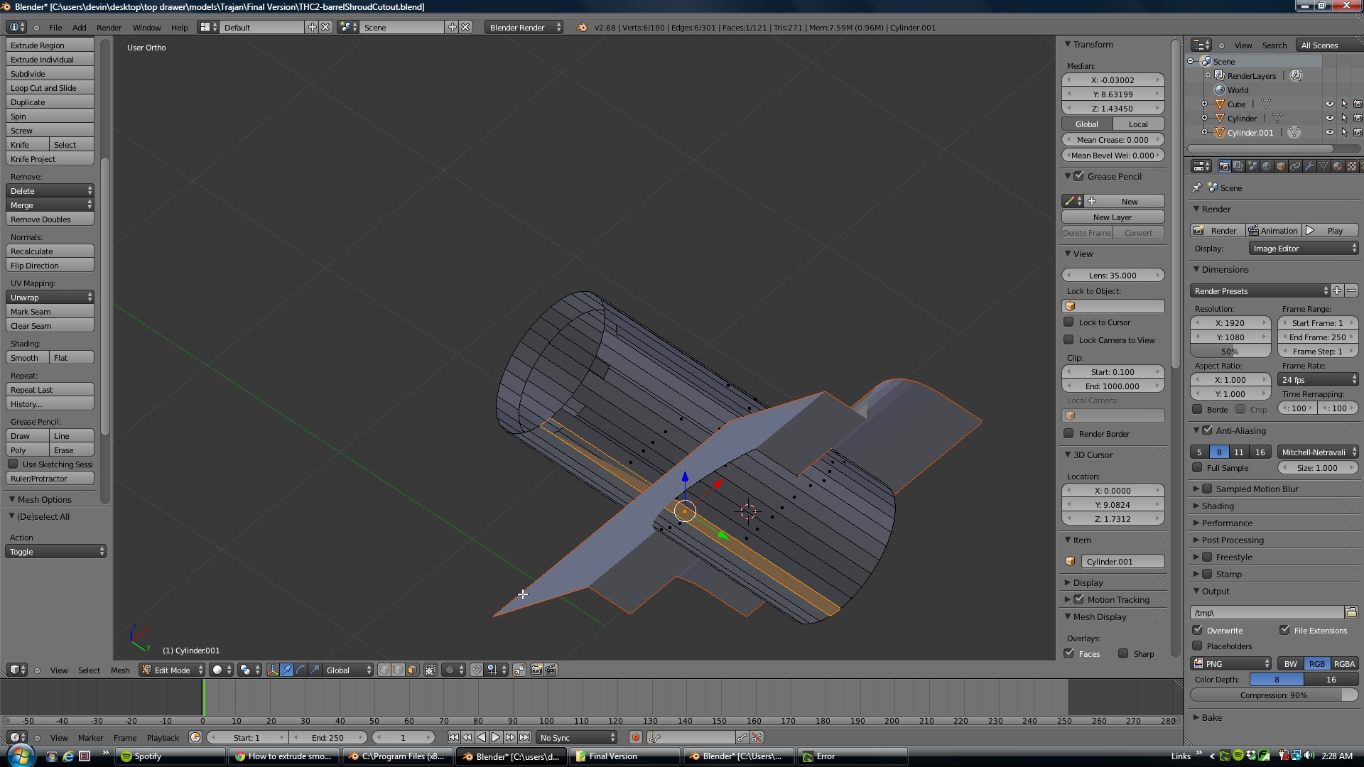
I just started over again tonight. This time I’m starting with the barrel which has a really funky shaped cutout barrel shroud. I thought I could just make a cylinder and then use knife project to cut it out the way I wanted but that’s not been working great. Here’s the brand new problem I’m running into by starting on the other end:
When I apply the knife project somehow it’s deleting a lot of faces and edges and making weird faces that don’t have edges. I don’t know what the hell is going on. I’m about to start over again
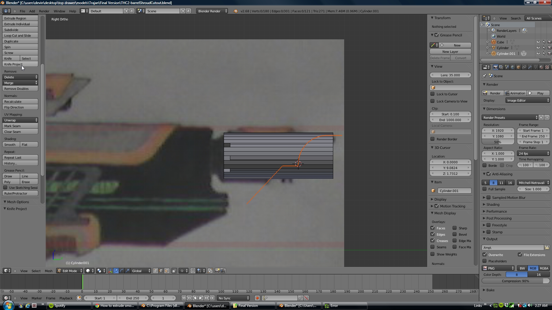
I think i see the problem on your screenshot : you’re using Blender 2.68, that is very likely be the reason : i remember the knife code (and so the knife project) was -very- buggy for a long time (missing half the cuts, cutting badly in many cases, etc…) it took a lot of version to fix and only recently since a couple of Blender version knife is finally been able to cut things relatively correctly.
Unfortunately as there’s no patching system with Blender to benefit from such bug fixes in 2.68, you’ll need to download a more up to date version, the cut through is probably a feature that got added to the knife project after 2.68 too, in my example i was using 2.72b .
In the case you need 2.68 for some export/import that does not work , try with Blender 2.72b or the recent 2.73 , the knife project should work -much- better. then once you’re finished with your modelling, you can open the blend back in your 2.68 (you can have several versions of Blender at the same time)
Also something that might have an effect here, my cylinder isn’t a single solid shape it’s actually a tube with open ends and inside and outside faces so it’s a more complex shape.
Version Stuff:
I figured it was probably something to do with the version but I was hoping I was up to date. Have we lost more import/export options in 2.72b/.73? I’m already using 2.46 for import/export because there are so few options in 2.68
Can the later version still save “legacy mesh” formats so I can transfer from them to 2.46?
Because I’d like to get rid of 2.68 when I update… can’t have too many versions at once… or at least I’d like not to. And would you recommend 2.72b or 2.73?
Difficult to not having too many versions, some addons that work great with one can be just broken in another, or an export/import format would work with one and not with another.
2.73 had a change that broke badly several addons at first, but some of them are being reworked to be 2.73 compatible (loop tools by example you can find a 2.73 compatible version of Loop tool in the related thread in the addon release board), and addon that will be made for 2.73 will not be compatible with 2.72b. So it’s basically up to you to see if 2.73 would be better than 2.72b depending on what addons you’re using.
I’m still working on 2.72b and i can tell it has still the “legacy mesh format” option to be able to open file into 2.62 and earlier.
How about using a Boolean? Using the shape you created for Sanctury’s method, just extrude that into a solid shape that is wider than the barrel, and use that as the object in the boolean modifier.


 [damn thing hardly ever does what I want ] rofl