Need Help with Landing Gear Rig

I am trying to setup a rig for some landing gear for a Grumman F3F-1 and am having difficulty. I am a noob at rigging. Basically the landing gear need to retract according to the drawing and video (seen this link). I cannot figure out how to get all the parts moving and the gear arm to bend inwards.

Can anyone give me some tips? I am there is a way to do this if I could get the rig, parenting and IK right.

Attachments


Check out Chris Khun’s rigging tuts on CGCookie.com. He has just what you need.

I am not a member there…the first tut was free but Parts 2 & 3 you need to be a member.

Me too - I cannot justify the cost for a mere hobby, Having said that - give me a day to look at this and I will post a mock-up here that you can work on. I am presuming that part no 5 is a compression spring inside a cylinder, if this is not the case, let me know sooner rather than later! It will be a fairly simple IK train, but you have to look at the IK section for the bones themselves to see what movement you are allowing through the IK train. and remember IK means Inverse Kinematics, so you drive the mechanism the opposite way to real life generally. For example you drive hydraulic cylinders by moving the arms rather than in real life you would drive the arm by moving the cylinder.

Here you are:

under-carriage.blend (434 KB)

Rotate bone “strut” to retract the undercarriage.
Scale bone “spring” to operate the spring mechanism.
Rotate bone “wheel” about its Z axis in Local Space to spin the wheel.

Make sure you are in “Individual Origins” mode not “3D Cursor”.

Don’t forget that when you rotate the wheel it needs to be a Scripted Driver with the forward motion of the plane over the ground in the appropriate axis, with a scripted value of “var / rad”, where “var” is the forward motion of the plane and “rad” is the radius of the wheel (circumference of a wheel is 2 * pi * radius, rotation is in radians). You can add a Cycles modifier to this driver to make multiple rotations (set the number of “previous” and “subsequent” iterations).

I have only done this approximately - I’ll leave you to fit it to your model and duplicate the other side. You can add bones “piston” and “cylinder” to the spring bone, make sure they do NOT inherit scale, but do inherit rotation, and then parent your two halves of the spring mesh to these bones. Use “With Empty Groups” and then select and assign vertices as appropriate. Here is a sample hydraulic cylinder setup to help you with this:

cylinder-problem-ver2.blend (714 KB)

Let me know how you get on.

Cheers. Clock

Wow! Thanks clockmender…exactly what I was attempting to do. I will reverse engineer this so I can learn from it as I model aircraft a lot. Your rig and tips are greatly appreciated! Five stars to clockmender!

You’re welcome. It was an enjoyable challenge!

Here’s Mk II version with the wheel driver and the offset hinge position for the strut and spring. It’s all there now I think. Just move the empty along the Y axis to see the wheel rotate. Still a crude model but that’s over to you. Let me see the results please.

under-carriage-2.blend (603 KB)

Cheers.

Clock

A couple questions…

Very nice.

  1. Did the bones have to be created in any special order? Which bone was the root bone?
  2. I see what appears to be empties all over, but cannot select them. What are those? Are they bone axis indicators? if so, where do you enable displaying those? If empties, how to select them?
  3. What is purpose of the plane-empty?

Thanks much. I will be working it as time permits. I will be sure to let you know how it goes.

No particular order is necessary - just get the parenting as mine, watch out for which bone is connected, inherits rotation and inherits scale as these are all important. Bear in mind that if you extrude a bone, the new bone WILL inherit rotation and scale, this is not always what you want so be sure to uncheck anything here that you don’t want, e.g. if the piston bone inherits scale from the spring bone, the piston will change size as you operate the spring, this you do not want, but you do want it to inherit rotation, otherwise the piston will not stay concentric to the spring bone axis.

  1. I see what appears to be empties all over, but cannot select them. What are those? Are they bone axis indicators? if so, where do you enable displaying those? If empties, how to select them?

These are not empties, they are the axes and names of the bones. Select the Armature and click the little body icon - you can then see in the Display Pane that I have Axes and Names checkboxes selected. see the pic below:


You can also select the STICK button if you want to see the bones as mere sticks rather than bulky Octahedrals

  1. What is purpose of the plane-empty?

This is an object to parent the armature to - in your case of a full model, I would either parent the armature to some part of your plane (risky) or parent all the parts of your plane to this empty, so when you move or rotate this empty, all the parts of your plane move in unison. The wheel driver uses the position on the Y axis of this empty to rotate the wheel the correct amount, just grab it in Y (select it, key g then y and drag it) to see . Empties are very useful for controlling movement of meshes as they are easy to assign drivers to, or assign keyframes to and they don’t render. :smiley:

BTW to see the Driver select the Graph Editor window from the left most icon here:


You can use the same icon to switch back to 3D view. I think that about covers it - Oh yes, to make the other side, select ALL the parts of this side once you have finished it, e.g. armature and all meshes, then copy and mirror them to the other side - then reverse the direction of the wheel driver (take the minus sign out) - EDIT - don’t take the minus out…

Cheers. Clock

For everyone else - this is what the plane looks like:


FLUF might be an apt description…

Thanks again Clock for all your help. I will read Witold’s article…I do have his e-book, but thought I would attempt doing this using an armature instead. Btw, the attachment link you posted doesn’t display anything.

Click this link to see a picture of the F3F-2 version.

OK I’ve done a bit more with the movements of the various bones, including some Keyframes. I’ll admit it is a VERY short take-off and landing, but you will get the idea. I have also added hydraulics with pipes to the cylinders to show you my method of doing this - again it’s not super smooth modelling, just enough to show you the technique. I have had to load this to pasteall.org as it’s too big for this site. Link is below:


You should have all you need now. Cheers. Clock.

This is awesome…really helps me understand how this should work in Blender. Thanks for the support. You can follow my progress here: http://www.military-meshes.com/forum/showthread.php?7182

You’re welcome - I shall follow your progress.

If you need help with the pistons let me know, I
ll post .blends, videos, and the links or just check my profile posts. I was just given advice by the community and figured out eventually a few ways to do them.

Just remember that landing gear mechanism (4 bar linkage in this case), all the pivot points relationship is very important for everything to fit properly. With the real device like this there are always adjustment screws to get the linkage to work in final assembly. One can not rely on machine tolerance only to end up with working mechanisms. So when rig is not quite working, play with pivot points.

By the way F3F landing gear shock is fully extended when stowed. That is not to say its fully out and floppy. It is extended to a stop and preloaded to keep its linkage length constant when stowed. When landing gear is deployed, geometry is ready to be compressed. And amount of shock travel seems to be small; about 4 inches as I can see. It is a stiff shock. Obviously shock should not be so soft that it let propeller hit the ground on hard landing.

Not to beat a dead horse but the tutorial I linked above is all about using empties, contraints, and parenting. If you do not want to join CGCookie thats cool. You can google Chris Kuhn and find many of his free tuts on the web. He also has a book on the subject of rigging without armatures.

Here is a free one from youtube: https://www.youtube.com/watch?v=nSe5woc45kA

I rig a lot of steam-engines, industrial devices from the 19th Century, and stuff like that. There’s a “Rigging Mechanics” tutorial here which is, I think, “still one of the very best,” even though it is old now. There really are just a few key principles to keep in mind:

(1) “The cart leads the horse.”
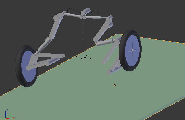
Even though, in real life, the motion of a piston drives the wheel of a steam engine, when animating that engine the wheel turns on its own and the entire mechanism follows. Usually, this is a combination of track-to and point-to constraints, usually limited to certain axes, always operating in a local-coordinate space. Things that “move together,” such as a landing-gear and the doors that cover it, don’t have to be literally animated-as-one provided that their moves are appropriately synchronized somehow.

(2) “Empties are your Best Friend.”
In actual mechanisms, lines-of-force are sometimes expressed at funny angles, with other parts of the machine’s frame compelling that motion to follow a certain oblique line. When animating such things, use Empties. An Empty is simply an invsible point-in-space, but it is also an object that can be parented, and that can be constrained. It is “a point ‘over there’” that can be locked to “something ‘over here.’”

(3) “Consider how you will have to control it.”
For instance, if you’re using the NLA Editor, you’ll probably have to animate the movement of a “control bone” with “actions” causing other things to happen as a result of that. Consider what level-of-control you’ll need, and how the device’s movement will be specified in the finished shot. If the same mechanism will be used in many shots, you must plan-ahead for all of them. (It’s very easy to “get it perfect,” then realize that you can’t control it. koff koff :rolleyes: )

(4) “Animate/Rig no more than you have to, to ‘sell the shot.’”
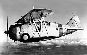
Unless this is an animation specifically meant to illustrate Mr. Grumman’s patent application, much of this mechanism is going to be concealed by cowling. (In any case, you choose where to put the camera.) Focus your attention only on what the audience can actually see, and consider omitting “the hard stuff” if there be any. Extreme close-ups of mechanical details, if there be any, can be treated as separate animations/rigs. “Cheat mercilessly.”

(5) “Take full advantage of my imagination, and of my understanding of ‘how things work.’”
Once you show me the device and show it starting to move, my imagination and my human-understanding of machinery will take over. For instance, “shot #1: the camera is mounted to the front of the airplane, and, as the plane ‘rotates’ into the air, the wheels start to fold.” CUT TO: “shot #2: medium-shot side-view of the airplane, taken from a following aircraft. The panels shut over the landing gear as the airplane banks away to the right.” The viewer doesn’t see it all, so you don’t have to animate what he doesn’t see; yet, he understands it all. The sequence shows exactly enough … meanwhile, the audience is scanning the skies behind the second shot, looking for that menacing German aircraft (which should appear in Shot #3). Pacing is everything.

It’s not that I don’t want to join CGCookie, it’s more about both Mrs. Clockmender and I not being happy with spending the money on what is a hobby. If I did this for a living I would be a fully paid up member of CG for sure. In return, I am keen to share my knowledge here to help others, not only Blender knowledge, but other useful skills, such as maths and mechanical engineering.

Thanks also to Sundial for his input here also. I know that I did not start the thread, but I have learn’t from the process as well.

Cheers. Clock.

I forgot to post this picture in the last post - just to show I do listen to and learn from, other people on this site. This model is mainly animated by empties, parenting, constraints, drivers, f-curves with modifiers and one or two armatures, like for the planet gears in the diff, where empties and drivers spinning in two axes tend to throw wobblies. Everything in the whole system works, including all the gear selection, using two empties to select the ratios or main gears, i.e. move the gear levers and engage the gears so the wheels move at the correct ratio to the engine), as do all the transmission, clutch and engine parts. This represents around 200-250 hours work so far. (I don’t keep an accurate record). I will post it to the projects section here once it’s finished - then it’s over to the bosses to say whether it’s accepted or not.


Cheers. Clock.