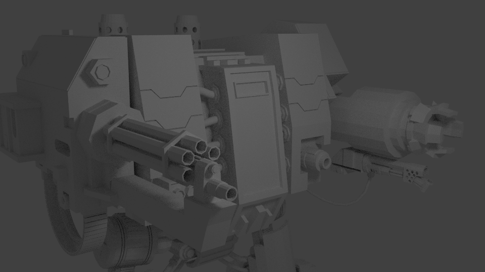
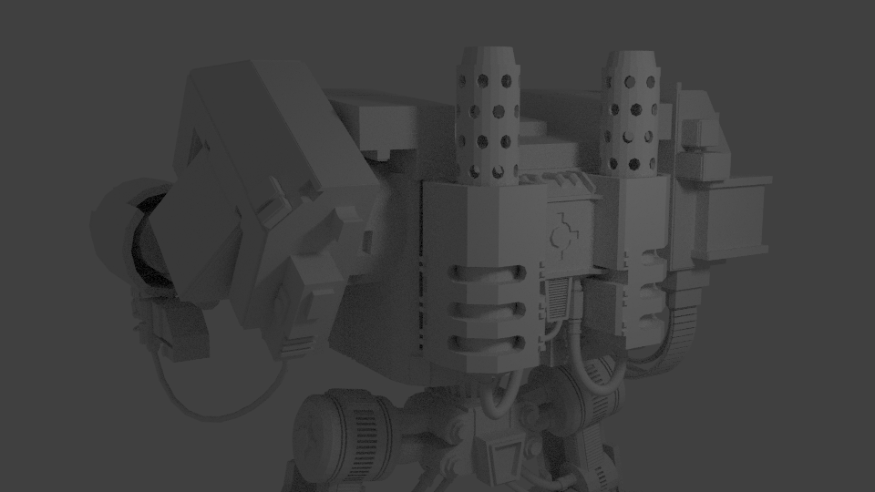
I have been working on a Warhammer 40k Dreadnought for about a week or so now and I have come quite far, but still have a ways to go. I have modeled most of what I plan to model (other than rivets) and will be looking to do materials and subdivision surfaces next. I also still need to convert all my curves into meshes so that I can modify them a good bit to make them look much better and fit the model a little better.
I am looking for some modeling critique of my dreadnought. I have watched a good many tutorials and have been modeling for a little less than a year (off and on). I want to hear what you guys have to say about what I have so far. Let me know if there are problems with my topology or if I broken any rules. I am guessing that I may have spent too much time modeling areas that will not be as visible as other areas, but I really wanted to focus on making what I thought would be “functional” and make sense. I used a good many images on Google images as references. I am open to any suggestions as to how I could improve my topology and my model in general.
Thank you for your time and I really appreciate you guys looking at my model. Sorry for the wall of text.
Thanks for taking a look at my model. There seems to be something strange going on in my pipe now that I took a close look at it. I have some non-planar faces on the open holes, and 4 of the non-manifold faces are in a strange place. I do realize that the mesh has quite a few non-manifold faces due to me using the mirror modifier, but the pipe in the back is an exception. I had hoped that those faces wouldn’t ever be visible in any final render I did of the mesh, but it is certainly a topology issue and I am glad you pointed it out.
As far as the shading goes, I usually don’t use smooth shading until I have added the subsurf modifier and then I start added “perimeter edge loops” as Johnathan Williamson calls them to sharpen up all my sharp edges and to add detail to my softer edges. Normal mapping is not something that I have ventured into much yet. I have mostly focused on modeling until very recently.
As far as the detail goes on using larger or smaller vertex counts on my circles/cylinders, I didn’t realize that I had used such a low vertex count on the larger pieces until you mentioned something about it. In the future, I will gear up my vertex count on larger round objects while keeping a smaller vertex count on smaller objects.
Thanks again for taking the time to look at my model
Ah, you’re going to use subdivision surface. Didn’t look like it so I thought you must be making a model that might eventually end up in a game and won’t be using subdivision surface with this. I must’ve missed that on your post.
Controlling the density and keeping an eye on the silhouette is still a thing with high polygon model to aim at some subdivision level (usually 2). Having to increase subdivision level just to get some neglected part of an object smoothed results to a lot of unwanted geometry elsewhere. But as a high polygon model there often is more room for real geometry so it’s not that bad.
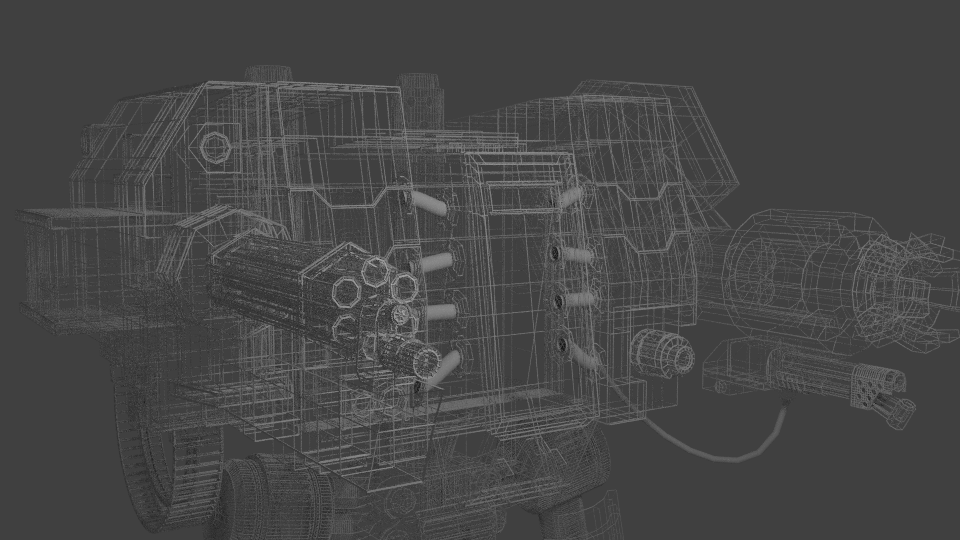
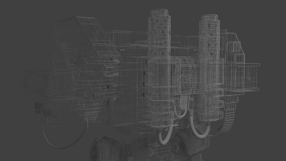
All models are purpose built. It would be important to mention the intended use of the model (still rendering, animation, game, 3D printing, other) and the direction you’re taking with it if it’s not the final model for that use. Also if you intend to give information about the model construction with a wireframe render, always show wires with backing solid faces because multiple layers of wires makes it a mess that is impossible to follow.
Yeah my mistake in not mentioning that it was meant to be a high poly model that was being made “for fun.” I will most likely just end up looking at it a lot and rendering it with different stuff in the background. I mainly made the model because it appeared to be challenging and would push my skills to their limits. Also good notes about the wireframe render. I have never been asked for a wireframe render before and had to look up a tutorial on just how to do that. In the future I will definitely render the wireframe on top of the model so that you can actually see what is going on. I also never go higher than subdivison level 2.
That was in case you weren’t using subdivision surfaces but keeping a polygon budget and concentrating detail to more visible areas.
With subdivision though, 6 vertices around a circle won’t make a perfect circle but it doesn’t always have to. Otherwise it depends on the detail and targeted subdivision level how many vertices to use. 8-16 for a perfect circle.
Wireframe render thing is a nice effect though. Might be even better with dark/black background and maybe lighter wires.
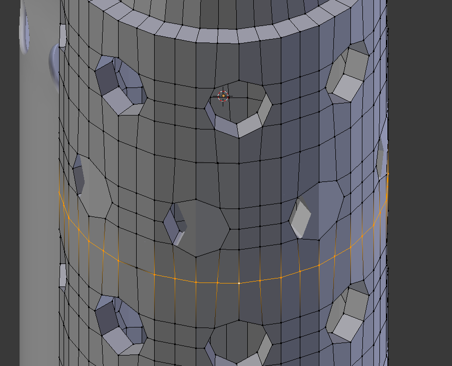
I found the problem with mine. When you select the edge loop below the second row of circles from the top you get 47 verts which is an odd number. When you rotate it a bit you will notice that something isn’t quite right. This is because there are two verts that didn’t merge here from the way that I created the rows of circles.
You created yours very differently from how I created mine. Did this take you a long time? It took forever to make mine. I created a special object that consisted of a set of cylinders that I used to punch the holes with using the boolean modifier. I then went and manually modified the topology so that there wouldn’t be a bunch of nasty triangles and such. Looking at yours, it seems that you created it a different way. I also noted that you are using the solidify modifier which is what I should have done and that would have removed the non-manifod faces. Yours also doesn’t have any non-planar geometry in it. I would very much like to know how you created it if it isn’t too much trouble. Thank you for taking the time to do this. I am glad that I made this mistake so that I can learn a more effecient way to solve this problem.
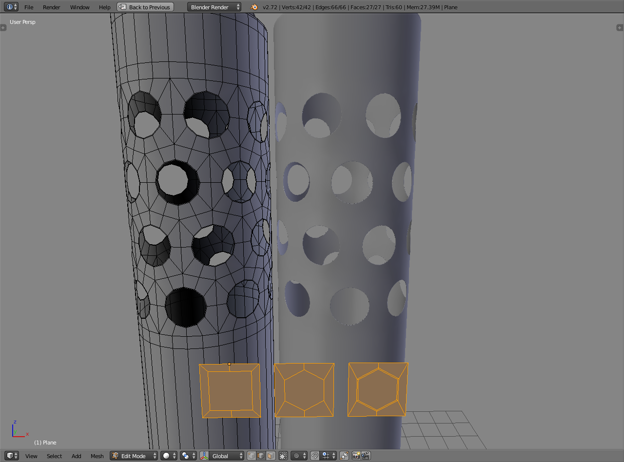
It’s not perfect. The tighter the curvature the more geometry you need in the control cage for subdivision surface to keep the roundness around the whole pipe while cutting a hole in it. I’m pushing it by removing quite a lot of faces, this also has poles with 6 edges (vertex with 6 edges connected to it), but should be good enough.
Modifiers used:
Array x2, simple deform - applied
Subdivision surface, shrinkwrap - applied
Subdivision surface and solidify left as final.
The way I removed “extra” geometry was to select a face loop inside the hole section, select similar -> perimeter, switch to edge select mode, select boundary and delete edge loops.
Edit: starting with 6 vertices around a circle gives a slightly better result because it further removes edges between the holes side to side.
This isn’t really the right forum section for this question, but the model looks pretty good. I would suggest that some of the gun barrrel parts are too low poly but if you are going to use a subdivision or modifier then this will be easily dealt with. All in all your model looks quite good but there is a particular problem i expect you will come up against quite soon, nasty little black triangles forming on your model when you render. These are caused by “bad geometry”, it is almost impossible not to have “bad” geometry somewhere on a model so don’t be surprised if it occurs. Fortinately there is an easy cure, if you get these weird shadings and black triangles appearing on your mesh when you render it then you will need to find all the sharp edges in your model and “edge split” them, this will “cure” your “bad” geometry. I assume you are fairly new to modelling(just because you only have 15 posts on here, from the quality of your work it seems you might have been modelling for a while) and it is one of the things i wish i had known when i was new to blender. By the way, i guess you will want advice for materials, textures and rigging of this model when you have finished the modelling. I may be able to give some tips for that.
@JA12 Thank you for making the video. I have never used any of the deform modifiers before so that one was new to me. I am guessing you get terrible distortion when you do not use the deform modifier before trying to use the shrinkwrap mod.
@jagdpanther The reason I posted in the modeling support forum instead of a different forum is because I specifically wanted advice/feedback on the topology of my model. I posted a separate thread in the WIP section with renders and information about my model. Thank you for your advice. I just recently figured out how the edge split mod worked. I have run into the issue you are talking about before with the black triangles, but I fixed it by correcting my normals.
I recently finished doing the subdivision surface pass on this model and found many flaws with my topo. Mostly I had issues where verticies had not merged properly and I had edge loops that wouldn’t go all the way around something, similar to my issue with the exhaust pipe. I also realized that I had added additional edge loops to some of my circles (the leg joints being an example) and have not been able to get them to smooth perfectly into a rounded form because of it. I have learned so much from making this model and hope that my next one will be even better.
Yep, I used subdivision surface modifier to get more geometry but that distorted the tube shape a bit. I used shrinkwrap modifier as a brute-force way to get the added geometry in place.
There’s more straightforward way though, giving it enough subdivisions before using simple deform. Removing the need for adding more geometry, removing some of it later on and also the need for making sure everything is lined on a perfect cylinder. Kinda obvious but it was late and at least shows multiple tools. I’ve made another one since, it shows the same with less steps.
If by problem solving you mean how to model, don’t know any specific to point at, going to need a whole lot of tutorials and pick up different things. From different tools to mesh requirements for different purposes.
Everyone has their own way of modeling. It’s because for any given modeling task everyone see a bunch of approaches to get from start to finish, a workflow that might break down several modeling problems to separate steps, and each of those steps could include different set of tools they’re aware of. There are many approaches and a plethora of tools that can be mixed in creative ways, which results to high number of different possible combinations. When you learn modeling you’re actually gathering options to choose from and updating previous ones as tools change or you develop different workflows, and never actually be done with that.
Where all those different approaches start to come together is when modeling decisions and steps support the future requirements for the model. It’s the model structure and organization that provides the functionality and makes the model good or bad for its purpose.
Learning all of that takes a lot of time so perhaps it’s best to limit the focus on something. Modeling with subdivision surface is a lot of fun and also teaches other skills, although still quite a big topic. Thing to note is that subdivision surface modeling is not Blender specific. Subdivision algorithm used in Blender (Catmull-Clark) is probably the most popular algorithm in most modeling packages and at least one option in its original or similar form. The use of it and model requirements are similar, which means you don’t have to stick to Blender specific tutorials unless you also want to learn about the different mesh modeling tools.
Couple of modeling problems with subdivision surface
N-gon with subsurf http://bit.ly/1joTtVr
Related simple topology problem and example solution http://bit.ly/1ogAswC

")

