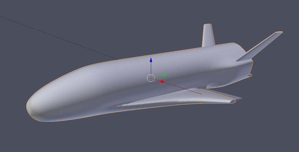
I’m working on my first Blender model (actually my first 3d model ever). Its the X-37B reusable spacecraft. I’d be interested in any feedback on where I’m at. I’ve included an image of the model just after applying the subsurface modifier but before any rendering.
I notice a couple of issues from the references that I have found:
The point on the rear of the wing, where it connects to the fuselage is very round. Too round. My images indicate that this should be a sharper contact, and the wing should not go so far - just the elevator.
The bulged area in the rear of the vehicle looks generally more defined than in your model.
The wingtips I have seen look to be more rounded, in your model to seems to cut off too abruptly.
Some additional views might be helpful, to see the rear and bottom of the vehicle. This looks rather good in overall shape, though. What do you plan to use it for?
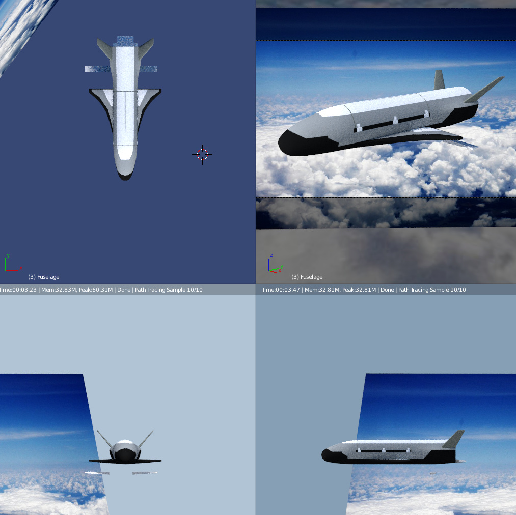
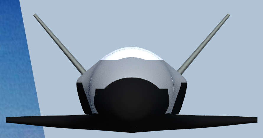
Thanks for the reply. I’ve been wrestling with the wing shape. I have about a dozen images I got off the web that I’ve been using. I worked on flattening the fuselage and pulling the aileron away a little bit. I think its better now. I went off some blueprints to get the shape and I think it matches up pretty well. It may be hard to see the bulge at the rear with no rendering. I’ve also tried to round just the front tip of the wingtip. I’ve included a quad image with some initial rendering. The images might be a little small but hopefully you can see some of the changes I made. Please comment more. I like comments!
I don’t know what I want to do with it. I think it looks pretty amateurish right now so I probably want to spend some more time with shaping and detail and certainly rendering to make it look more realistic. But I need to learn more obviously…
Quite a few images indeed. The wing shape does look a bit strange, I agree. Ultimately the model here does not need to fly, but closer to the actual craft is usually preferred. I made and airplane once, and the control surfaces were all difficult to get looking quite right, being too thin or thick or otherwise weird, and sadly the images usually available fail to capture most of the nuanced shape in the wings. You do appear to have something of a seam near where I imagine the model is mirrored, that gives a sort of peak to the bottom, which should be nearly flat.
It seems that you might could get the wing tips to cut off more gradually if you scale the vertices there to zero on the z axis (s+z+0), and maybe do some loop cuts and shaping to get the curve right. They look to be pretty thick, right until the edge, on the real vehicle. That seems to go for the tail as well, though not the part directly beneath the (yet (I assume)) nonexistent engine nozzle. Alas some of the images I am finding are inconsistent it would seem, fins sloped at different angles and that sort of thing. Maybe just my perception, or maybe different models.
As far as texturing, you probably can do a lot of work on that before my observations can be of much aid. So far, I imagine it might look right viewed from very far away…
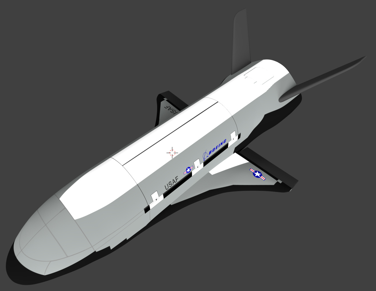
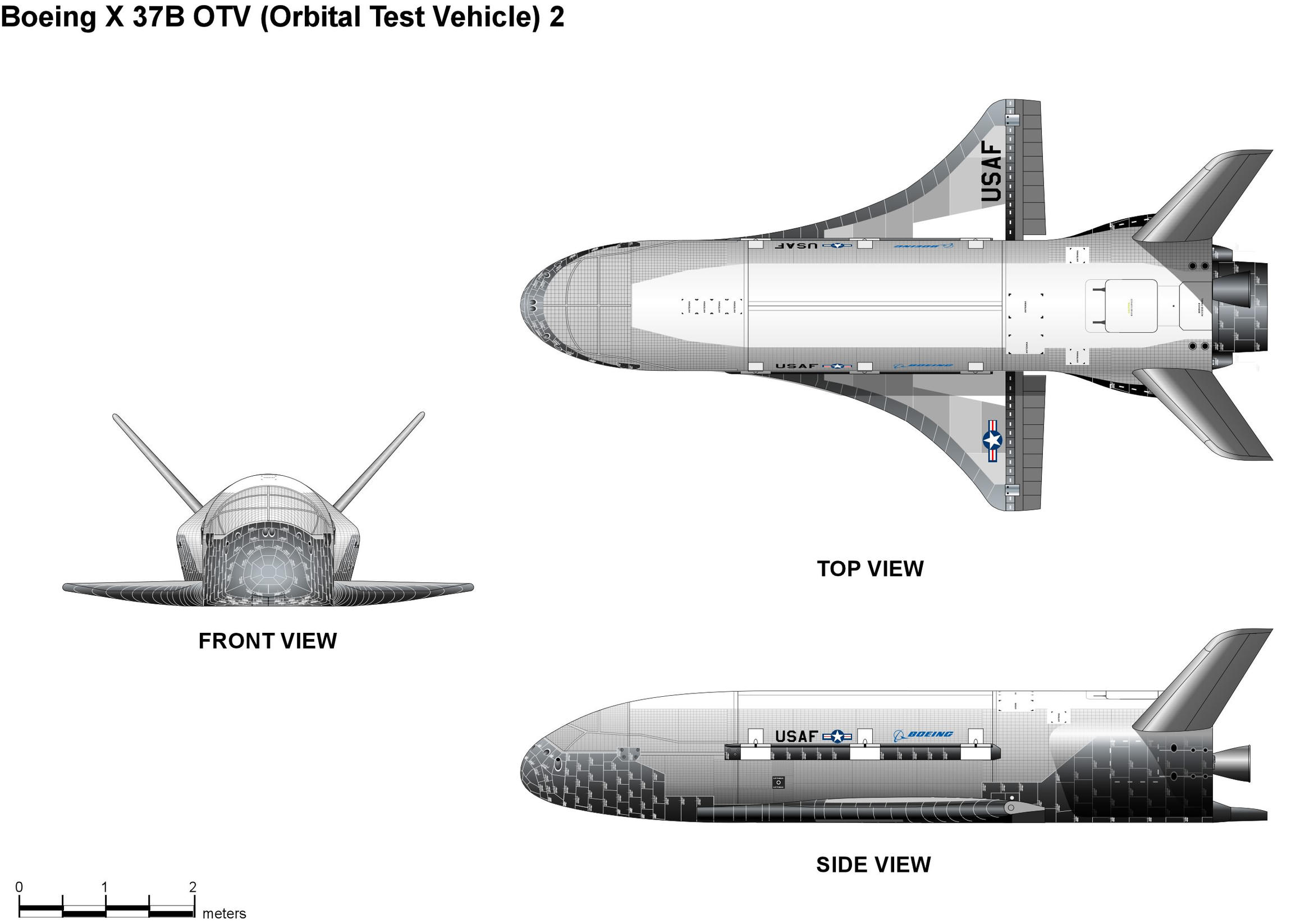
This image comes from wikipedia, you may have found it already, but I thought it was helpful for my observations.
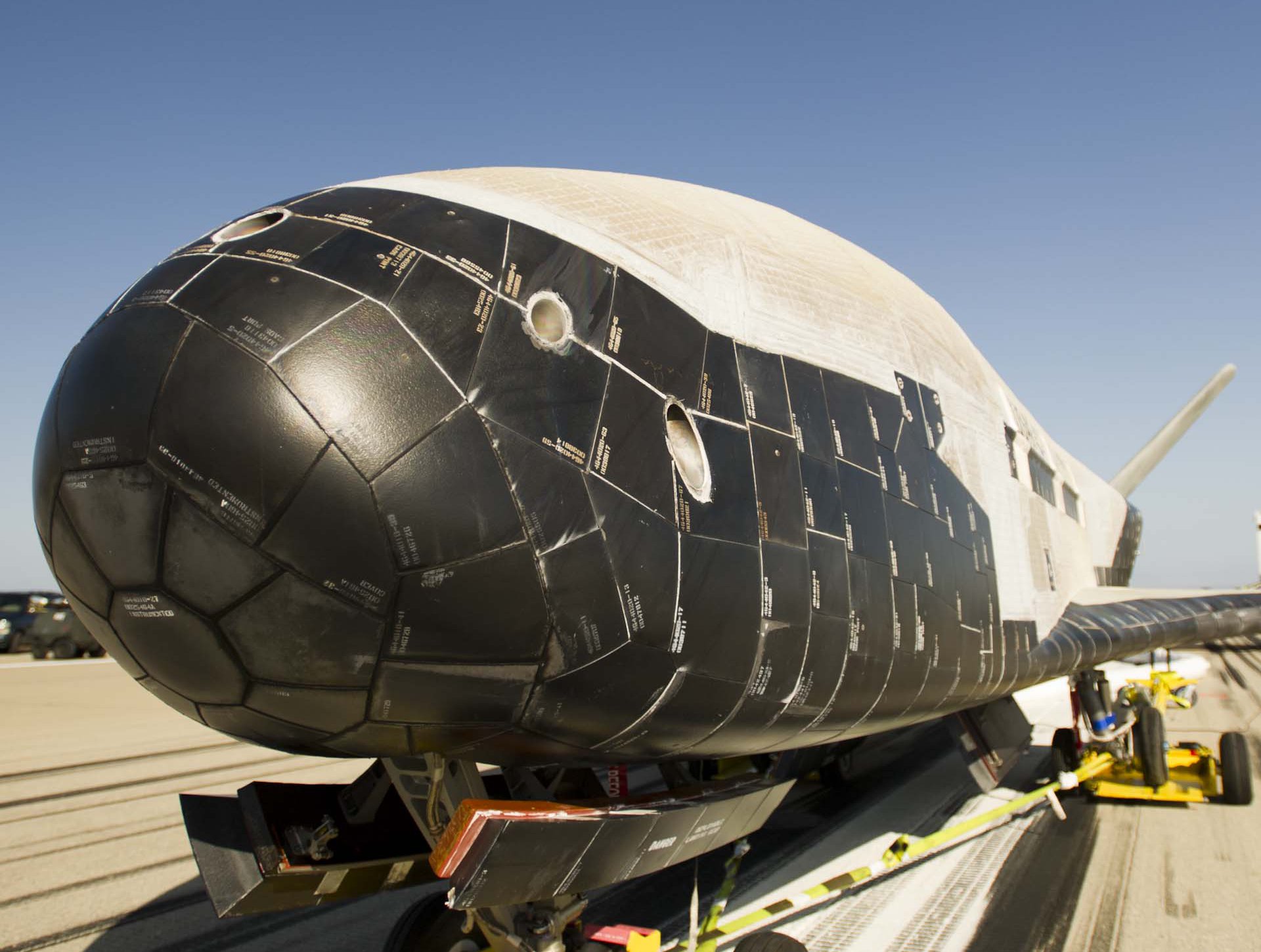
Will you add the RCS ports in the mesh? It seems to me as though they might be difficult to do realistically for close up images using only bump/normal maps. That would be though, I guess, a final touch to the model.
An image that shows the RCS ports on the nose fairly close up. If you do not know (for all I know you build spacecraft for a living), these are ports for jets that maneuver the spacecraft around, especially needed during orbit.
Wow, this blueprint is alot better than the one I was going off of. I think I’ll start my shape over based on this image! It even has the tile shapes and such. I’d really like to get the tile detail in there as well. Any suggestions on the best way to render those? I did my initial rendering painting on a UV unwrapped images.
One question. I did the original fuselage shape then sliced off half of it and used the mirror modifier after that. Do you think thats a good approach or should I do the whole thing?
This is a really kewl video tutorial. I had used UV unwrapping to do the initial rendering. I didn’t know you could layer textures. Seems like I should do the paint as on layer and then try to do like weathering and wear from flight in another layer?
Interesting spacecraft!
(I noticed that in post #7 you wrote “image”, not “images”. Did you follow Andvari’s suggestion and visited wikipedia article? There is another image, containing remaining: bottom, rear, and right view…).
About your question on mirroring: I think that ultimately you will have to apply the mirror modifier if you want to paint it as in post #5 (i.e. creating the “real” mesh of the other side of this model). The reason is simple: the insignia and labels on the left side are different than on the right side.
However, first unwrap everything you can of this halve. Then create its mirror copy (just saving the time required for unwrapping the symmetric half of this mesh).
I would suggest to recreate the tiles using bump maps (in Cycles they are quite efficient).
About RCS nozzles: if you are using subdivision surface modifier it is difficult to make precise, rounded openings on a curved surface as on this nose. In such a case maybe the following method of recreating these nozzles will be effective:
create their openings using a transparency texture (yes, you can “cut holes” in the mesh mixing your basic material shader output and a transparent shader, and using a B/W image of holes as the mix factor);
model the inner cones of these nozzles “in the mesh”;
I used similar approach for making various small openings in a WWII aircraft model (coupling the transparency texture and a simple model of the inner walls in the trimmers of this P-40B). It is also described in details in this book - you can skim fragments of its English edition in Google Books [SUB](description of transparency textures starts on page 444, but in Google Books you have type page number 434 to get there)[/SUB]
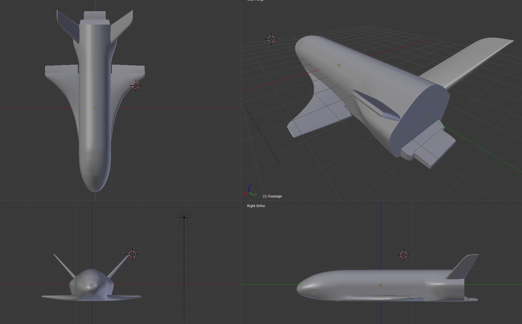
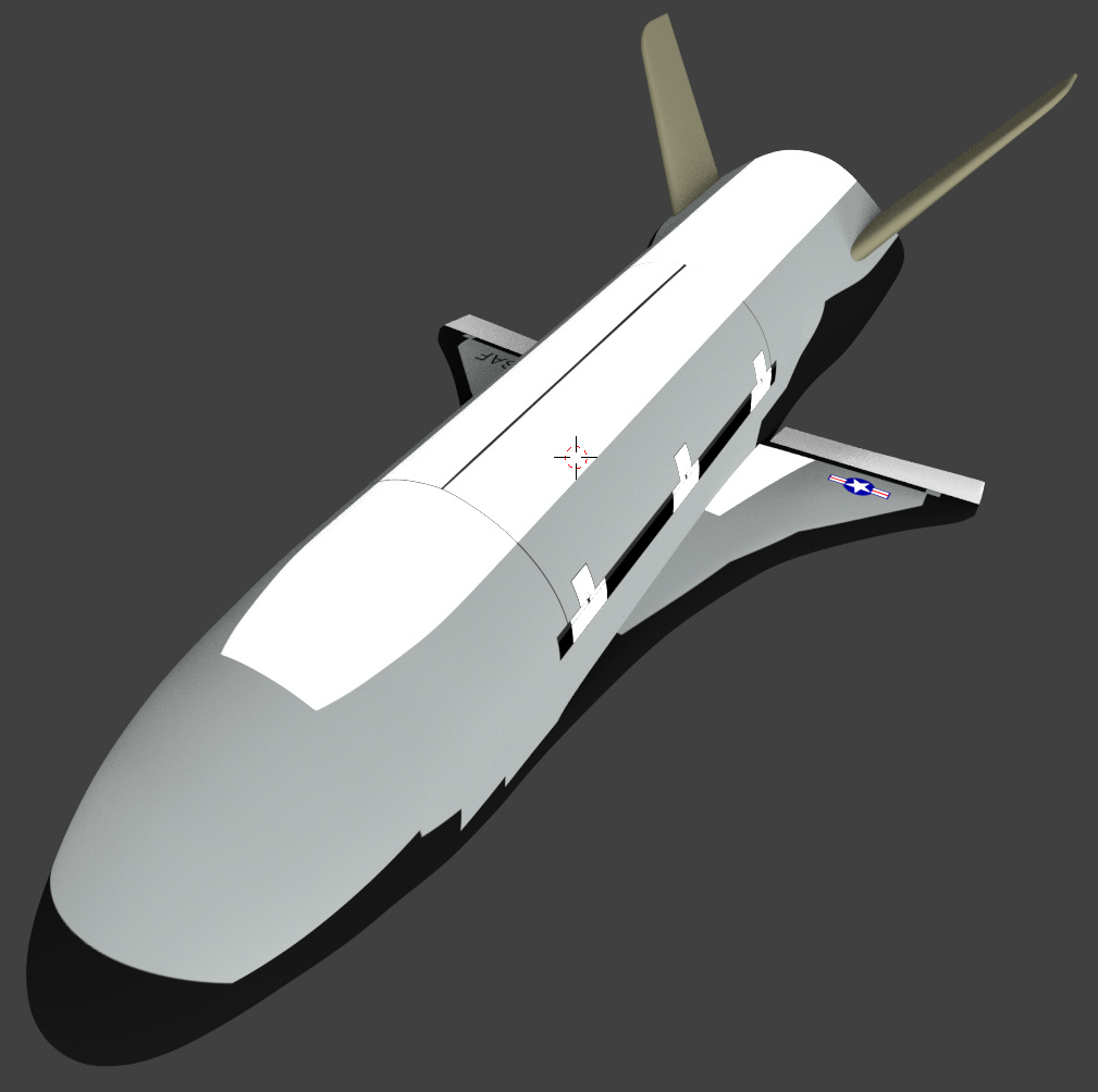
K, here’s an update. Let me answer a few things from previous posts first.
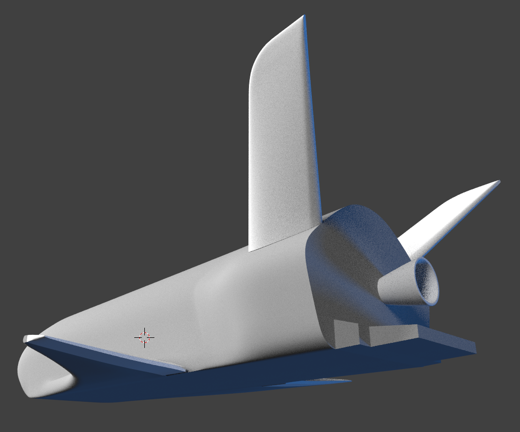
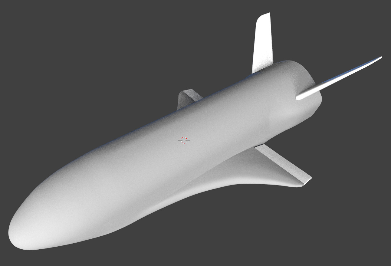
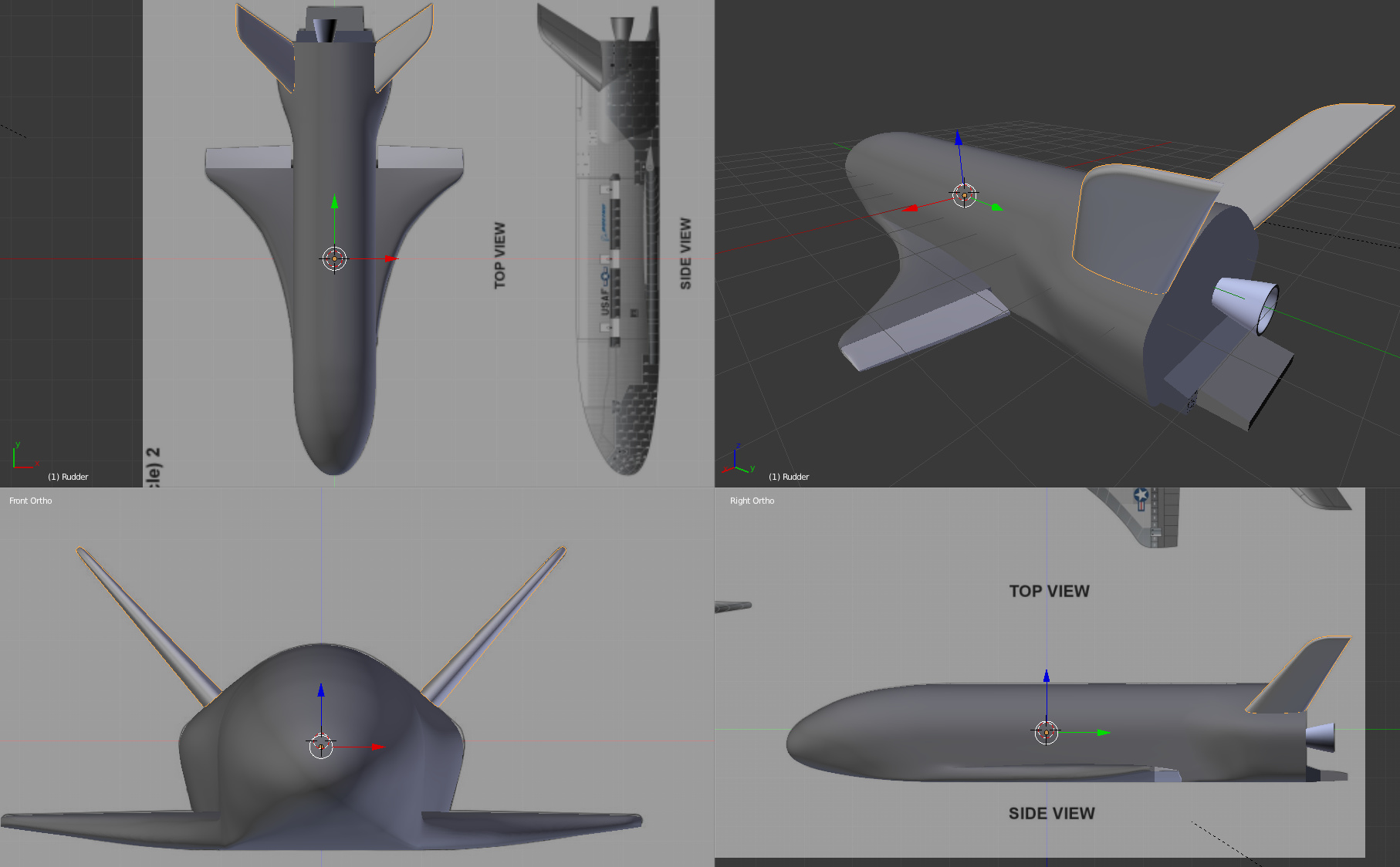
I started the shape over based on the new blueprint. It made things alot easier and I think the result is better. The fuselage, aileron, rudder, and lower tail section are separate objects. All but the lower tail section are mirrored. I’m pretty happy with this shape (there are alot of subtle curves that took time) but I’m looking for comments! Once I get this, I’ll move onto rendering. Thanks for the suggestions so far!
Must remember to look back here once this is finished, i look forward to seeing this in full detail. That heat shield tiling on the underside of the nose could be tough but would look amazing if you can do it.
As far as the RCS Jets, my thought was to use the knife tool to place some vertices, then shape them and extrude inward? Have you tried anything like that?
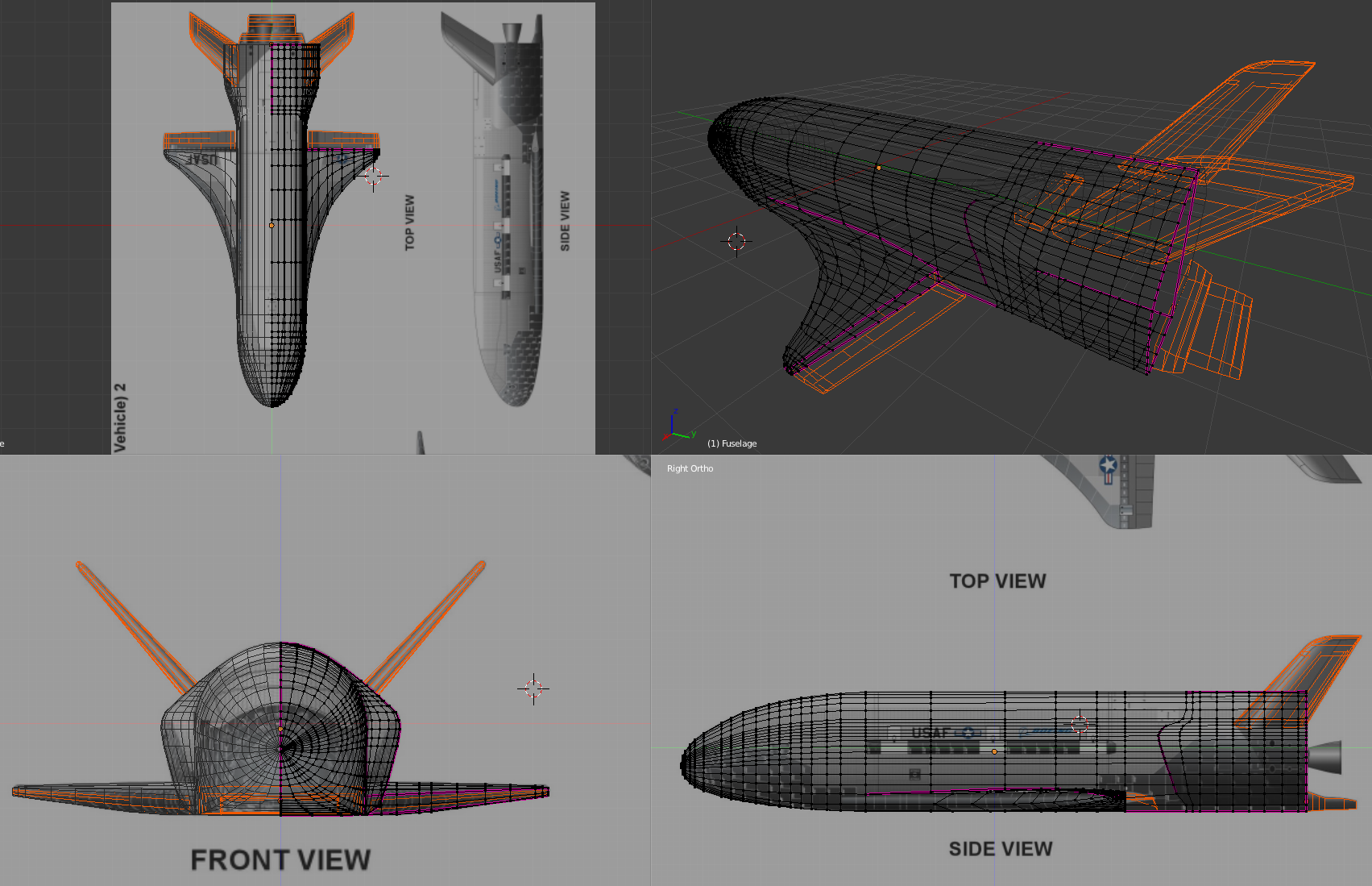
Also, for everyone. One thing I’m wrestling with are some flattened ridges along the fuselage that are appearing because there is a slight crease needed on the leading edge of the rear bulge. These flattened areas seem to become more pronounced as I increase the subdivision factor. Any suggestions on how to get the curve back? BTW, Here’s an image of the mesh for your dining and dancing pleasure…
That does look quite a bit better. Still missing the main engine nozzle (which, I imagine that you already knew). There is a bit of a visible seam from the mirror near the back. Other than that, the details that I checked all look rather good.
The back panel I am uncertain about, but it seems that you likely are right in leaving it essentially flat in this version.
Andvari: Thanks! I’m wrestling with exactly how creasing works with the subsurface division. If my other post ever shows up you’ll see the mesh and creases I put in. I’m not sure I have the hang of creases completely yet. I think the creasing is responsible for a little bit of the flat facets along the fuselage as well (again that I mentioned in a reply I put up hours and hours ago but hasn’t appeared yet). I will be putting in the rocket nozzle as well as some more detail on the back panel but it appears to be completely flat from the drawings. Thanks so much for pointing me at the better blueprint drawings, they were a big help!
It looks to me as though some of the weirdness on the side of the fuselage may correspond to the higher number of lines in the wire frame. I have had this happen with some modeling experiments, but am not really sure of how to fix it, except maybe by selecting the lines and dissolving them (accessible when you hit delete). It can also work to instead of always creasing, add loop cuts very near by to the edges you want to sharpen.
Glad to have provided the schematics. I have spent copious amounts of time looking for drawings of that sort for other (non Blender) projects, and it invariably helps to have good ones.
Well, probably it will create some n-gons on the faces around nozzle holes. If the surface around is flat enough, the eventual deformations will be negligible. Just try it, but keep a backup copy in a case you will be not satisfied with the result. [SUB](Every opening/sharp edge on a curved surface deforms its shape. See the last pages of the Appendix where I described the properties of subdivision surfaces)[/SUB]
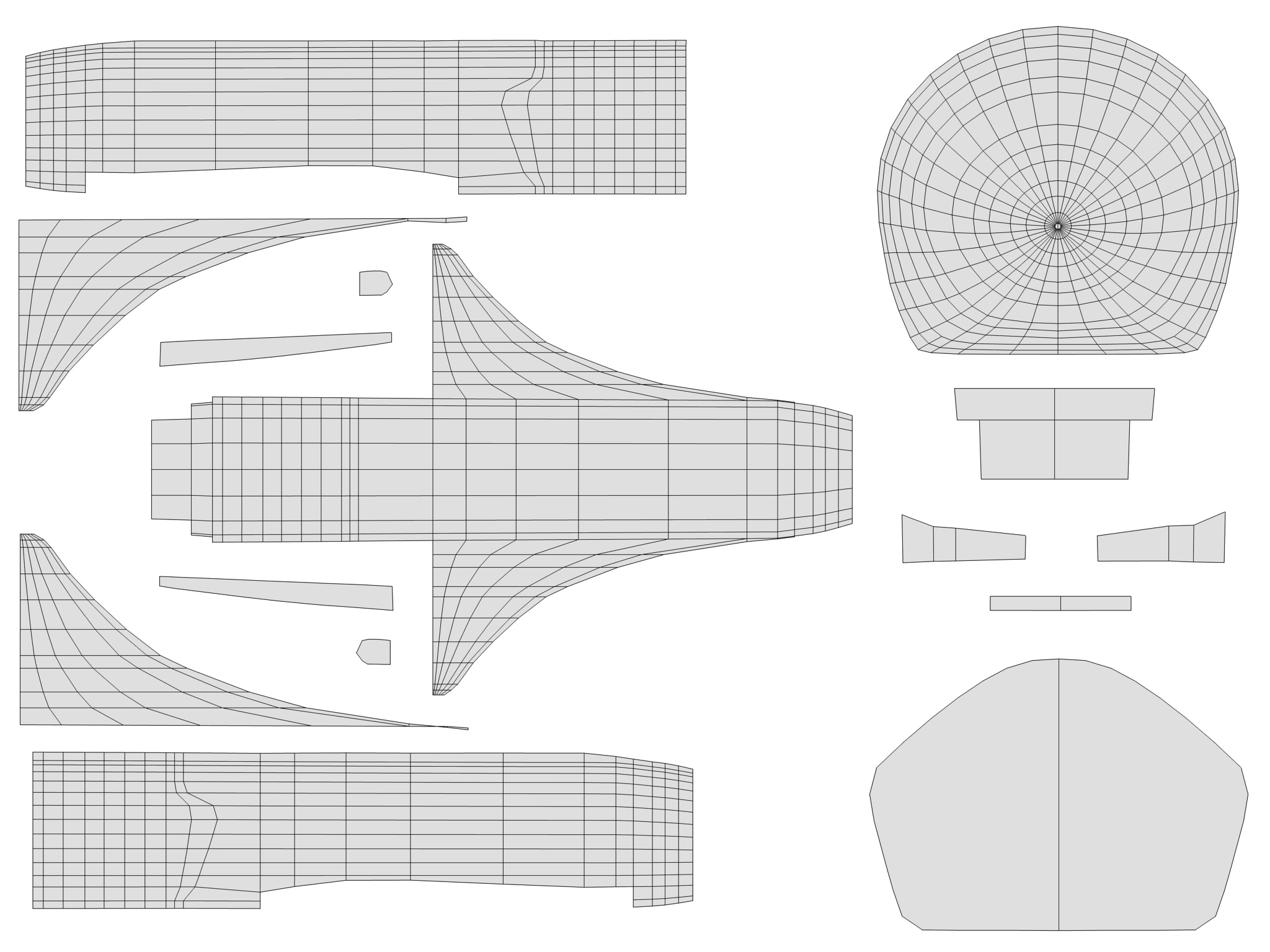
Here’s the UV unwrap of the fuselage, wings and tail (which are all one object). I applied the mirror to get back all the points, then unwrapped both sides separately so I can get different graphics on either side of the vehicle. I did a front view so I can work on the tile detail of the nose there. There’s another simple UV unwrap for the aileron I didn’t include. I’ll just use materials for the rudders and nozzle.
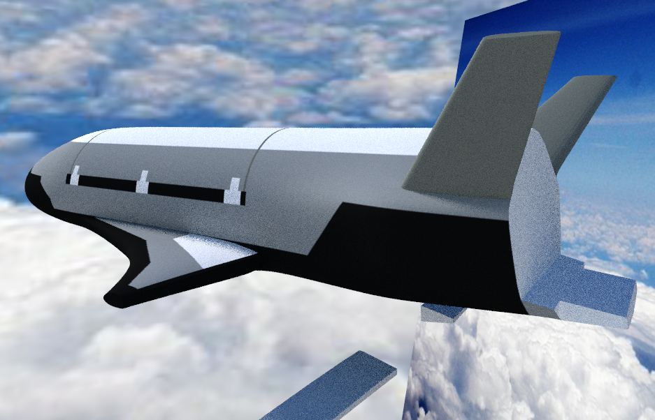
Here’s a quick screenshot of my current render state. I did this quick with Cycles and 64 samples. Just trying to show folks how its going. Please make suggestions!