I have found myself firing up blender to relax because now I know enough keys. I plan to use this energy to model a kart–hot rod (Model T) crossover in a slow pace.
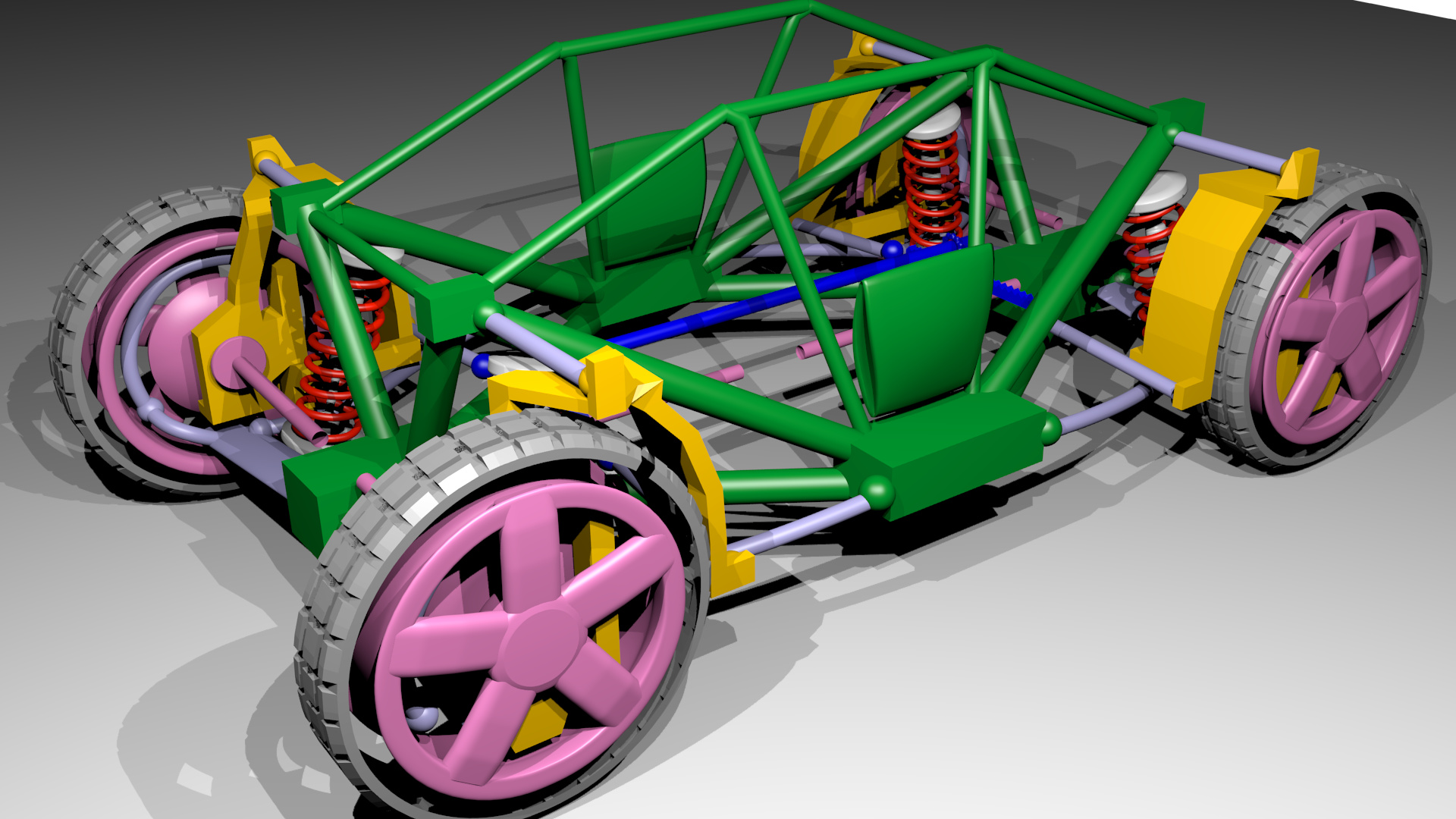
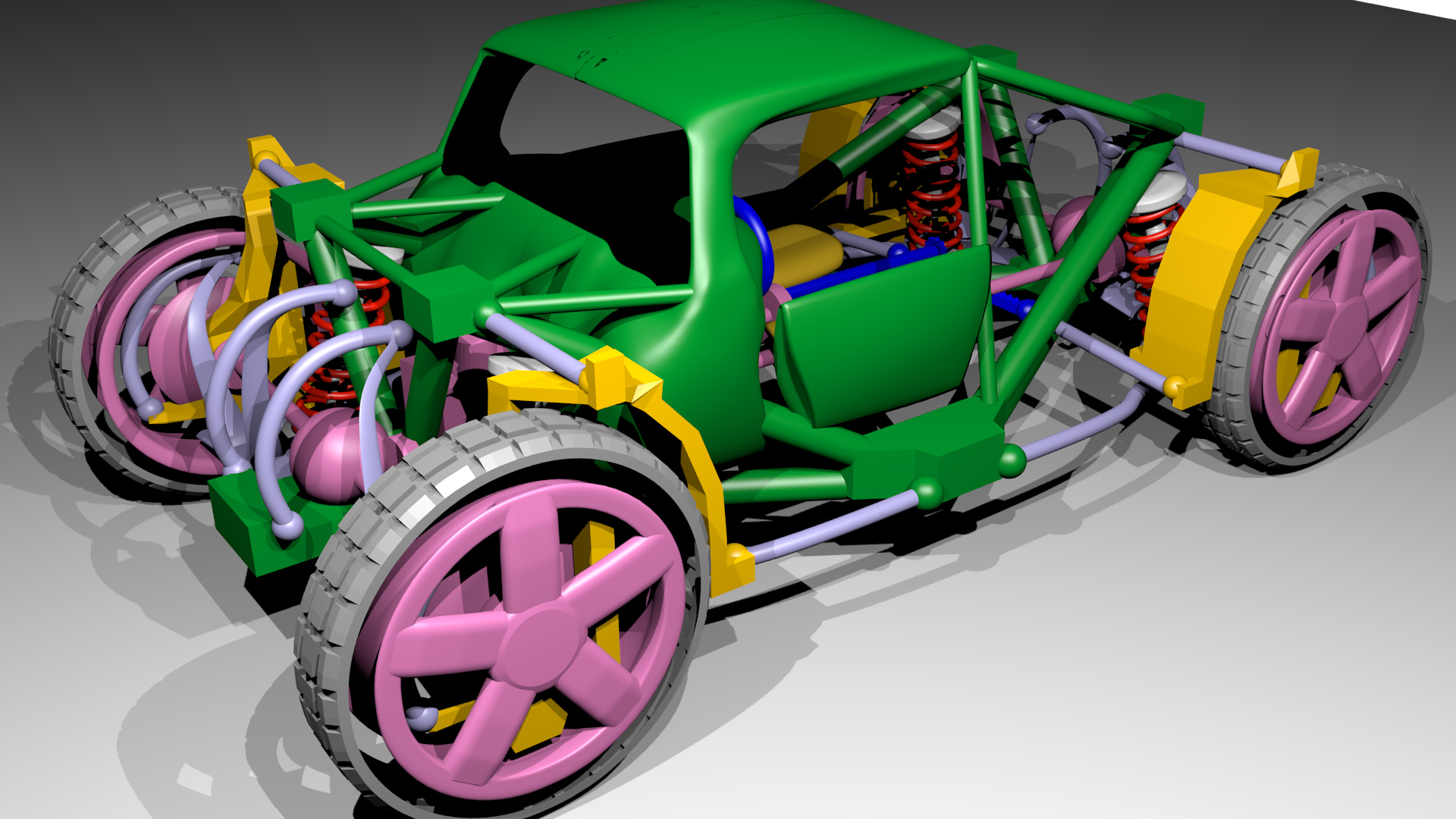
There is such a large zoo of different suspensions for 4-wheelers all with pros and cons which can be explained by theory. I want to model a suspension based on theory (the other way around). Simple suspensions can work well, but I’d like to draw one which works well in curves, keeps the wheels straight on acceleration, and up on suspension travel. For minimal bump-steering a parallelogram geometry like double wishbone would be ideal, but the variation with longer lower wishbone and shorter upper wishbone look better and have somewhat better chamber at high speed cornering. I like longitudinal connection rods in rear suspensions and in hot rod front suspensions. Using them necessitates ball joints(instead of flexible joint which I like more because it needs no grease) on the lower wishbone, which looses its wishbone shape, andbecomes a transverse connection rod. A long time I thought I would need a U- joint, which conflicts with the goal of ultimate stiffness on this connection rod. But then I found out that real suspensions use two (stiff) ball joints and half of a U-oint(called “integral link”). This construction is less stiff on twisting, but the twisting axis is parallel to the rotation of the wheel and not noticeable. Steering would be by means of rack-and-pinion drive. For perfect chamber, at least on flat surface at low speeds, the rear wheels also need some chamber on turns. It seems to be unavoidable to use a rack-and-pinion drive on each axle.For example a longitudinal shaft would lead to the opposite of a progressive steering curve. The steering axle is supposed to be centered on the wheel, no matter if it is left or right. Thus the rims have to be of that variety used in cars with spokes on the outside, and not the bicycle ones sometimes used on pedal driven trikes or bike-trailers. The disk of the brakes need to be thin that means no internal vents, in fact I’d like to use plain rings and 3 hydraulic cylinders in order to make it look more like a hydraulic clutch. Lets just assume the four wheel drive helps with braking. I even thought of inboard brakes like in DS 1 or E Type, but: “safety first”. I want a carriage / pedal driven trike look for the tires.Thus there is a conflict between the sleek look and the steering axis. I will have to pack everything very thoroughly. All-wheel steering leads to symmetry, which I like. To perfect symmetry, I’d like to also add all wheel drive. The body and possible the mid-engine&gearbox break the symmetry a bit. The steering axis is centered longitudinally on the rear wheels, but a bit in front of the center on the front wheels to make the steering wheel return to neutral. This may be difficult to implement with a Blender modifier considering that all joints inthe rim have to be adjusted. The suspension is connected to the body on as few as possible hard points. The long lower wishbones of each axle share one point below the differential. The longitudinal struts of the two wheels on each side share one point. The coil-overs end close to the upper transverse connection rod.
To show of it suspension,the car has to be an open wheeler. To be street legal, these still need fenders. Some cars sport light unsprung fenders (how to model CFC with clear finish?). These allow to place joints outside of ther im and to still keep them clear from debris from the tire. In this way the upper transverse connection rod can easily be placed in the right height for the coil-over. I have seen joints at this position on production cars and on buggies, but with joints full of dirt. In some cars the rack-and-pinion drive is just behind the dashboard,which keeps it clear from a front engine and the feet of the driver,but leads to a joint to the wheel next to the upper control arm,while it would look better at the low arm. Additionally, a four wheelsteering must be placed lower. To show off its axles, these are far on the front and far on the back and there will be no conflict withthe driver feet in this car. The engine needs to be behind the driver or of a small inline geometry in order not to obscure the all wheel steering and drive.
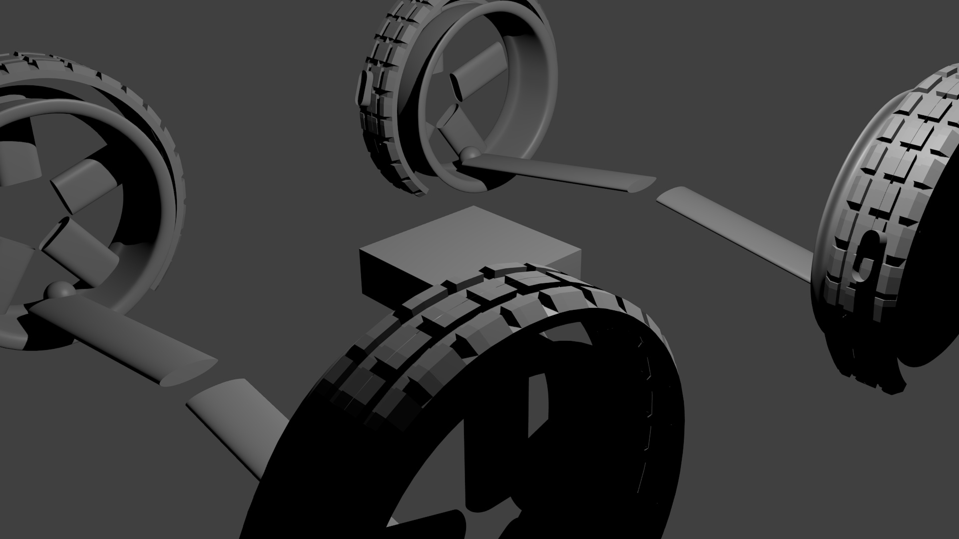
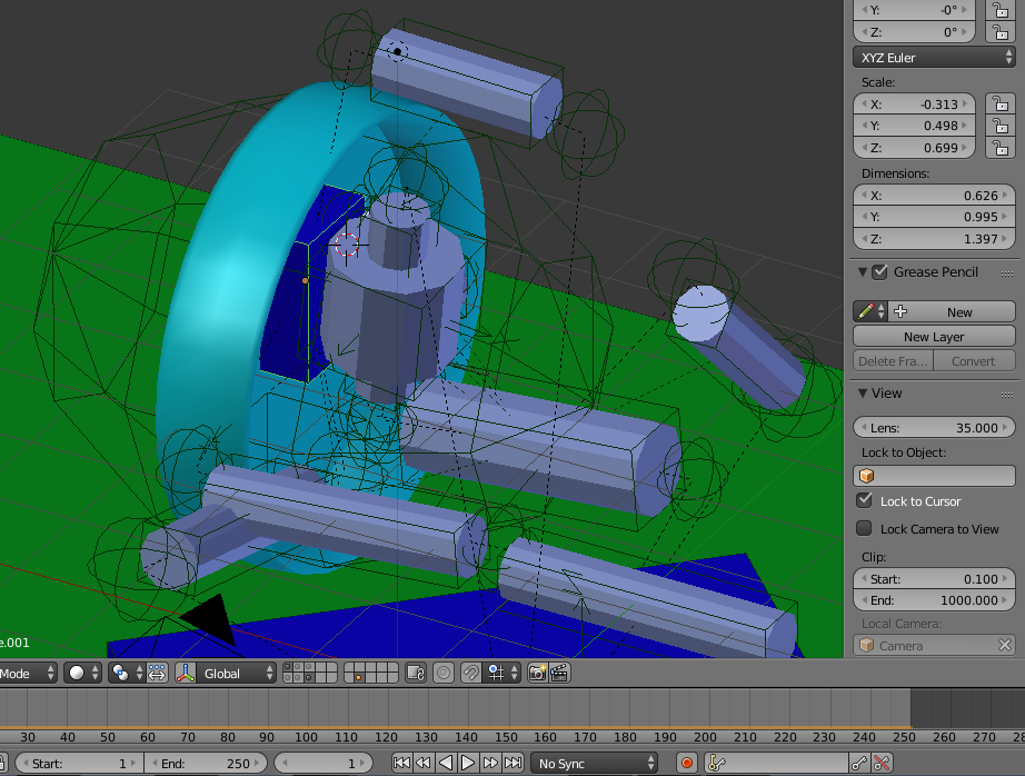
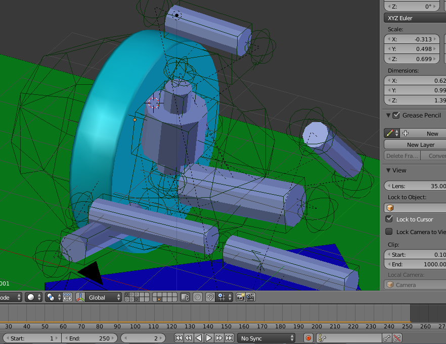
I had the idea of showing ball bearings by means of faded in transparency within an image sequence. But Blender wants the bearings to be a single mesh or it cannot duplicate them. Thus: No bearings. Still, to show the integral link or to explain the different aspects of the suspension, I need to make image sequence with a smooth moving camera and then some animation, which I have not done before in Blender.
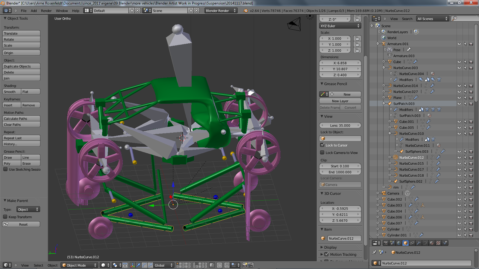
In the past I was only concerned with the geometry, but after seeing some of your great cycles renderings I also want to make a realistic version. Last time I checked cycles was to slow on my machine for a long image sequence,so I will render only some images that way. Also I plan to fade in some lines showing the axes of the wheels and how they meet all in one point on the tarmac (at a typical curve radius). I read that Blender has key-frame based hide mechanisms in the outline and I will use that. Struts will be modeled as NURBS with bevel and taper. The sheet-metal body may consist of NURBS surfaces although up to now Icould not solidify them nor weld them in a realistic way, which willstand out if the camera passes close to them.
The project is to be CC-BY-SA. I will find out how to put text notices about this into a blend file and how to import other CC-BY-SA assets. I already uploaded all my Blender stuff and will only stop if someone pays me.The problem with renderings is that no derivative work is possible and there are already too much images on the internet. I like thecar-bibles, but cannot rotate their 3d models, nor is there an immersed navigation, where a complete car is shown and the camera can fly to specific parts of it. The tires will be probably based on that Guru tutorial hopefully in this blender version and with proper parenting without the need to bake in (similar argument as with the rendering).


 . Glass works. After dusting of the CPU, Blender was able to finish the rendering. I incremented the date already to express the new chapters: rig and cycles.
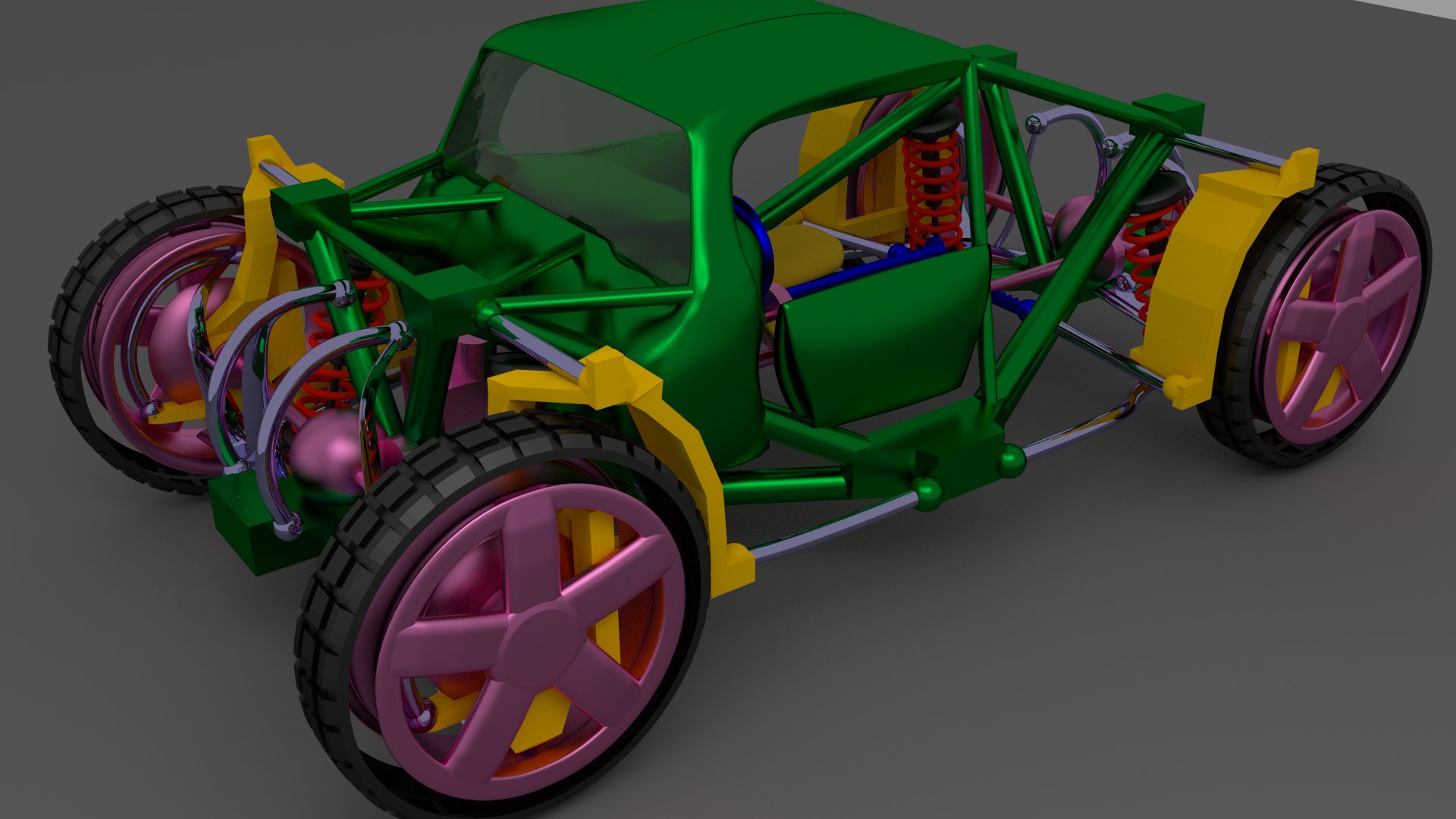
 I mean like for example the shoulder in a real human skeleton. I tried to use constraints. I understand how to constrain a bone to a fixed object, but in my case there is nothing fixed as the car is supposed to be driven off road in a future image series. I do a number of complex edits, switch between 3 edit modes, and in the end nothing works. And I fail to model the symmetry braking due to driving. You know like chemistry, where a molecule has a high symmetry, which is then lowered by a vibron. I looked into a crankshaft tutorial. I am sad that I could not find a blend file for download and had sit through the movie and try to listen to the guy repeating steps. I could switch the project and model a V12 as a replacement for the V2 above to test if I understood that tutorial and offer a download.blend And the game engine, which might be more suitable for a racing game, renders nothing.
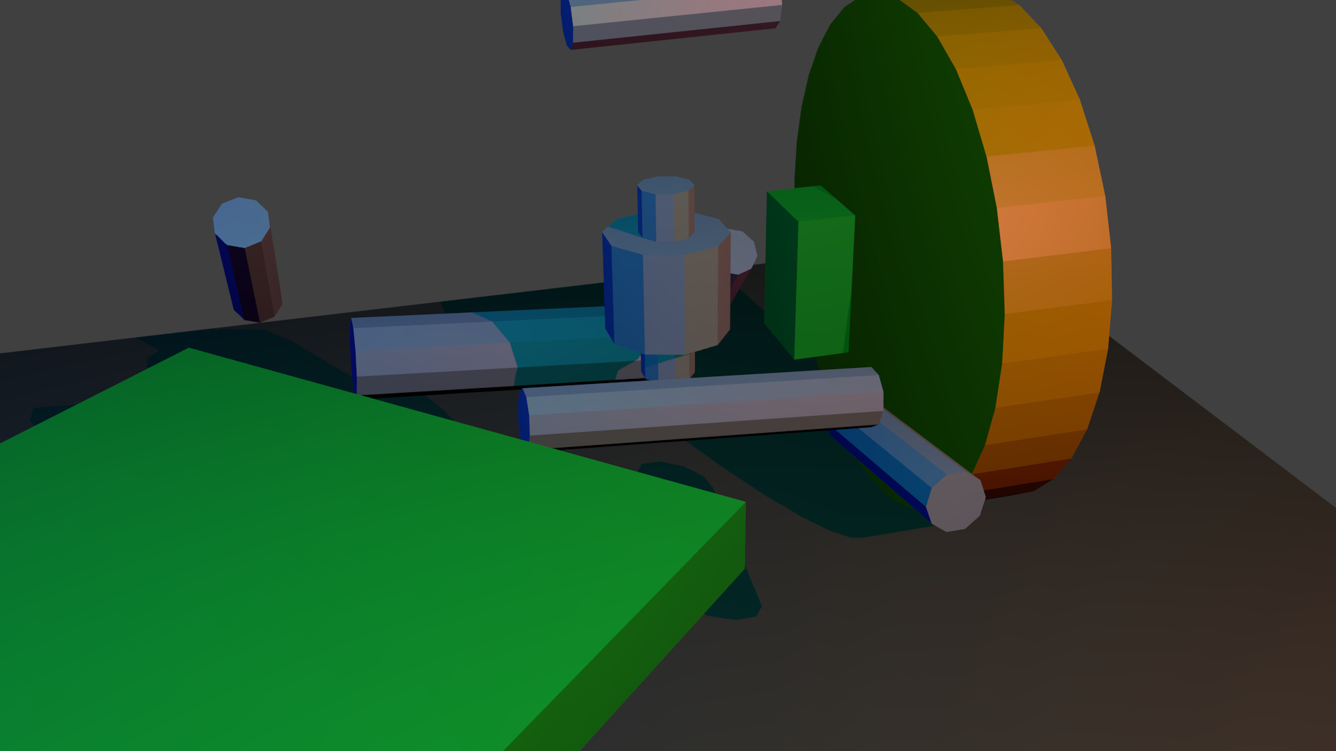

 Also active is more fun. It is for racing and not for security. In 10 years google drives you.