So, this is the sort of modeling problem that drives me nuts, and I’m curious how you guys attack this sort of thing.
It’s aggravating because it should be done with parametric modeling, not mesh-based modeling.
But I don’t plan on getting Rhino any time soon. So…
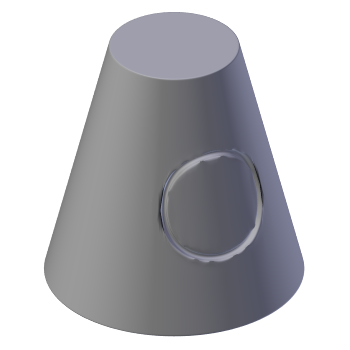
Here’s an example of what I mean:
Insetting this circle into this truncated cone results in ugly shading problems, pinching caused by uneven mesh density.
Are there any tricks for getting around this, besides going high-poly and booleaning the circle in?
I have some ideas that might work for limited cases, but was curious if there are any proven techniques or best practices.
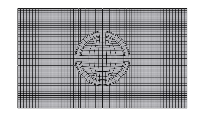
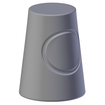
This is the best solution I’ve been able to come up with so far - modeling the whole topology of the cone in 2D first and then using the classic Warp tool, then Proportional Editing to stretch it back into a cone shape, but there are some problems with this:
I had to rebuild my original shape entirely.
It may not work at all with more complex geometry.
Maybe there’s a way to use the Shrinkwrap modifier to solve this, but I haven’t tested extensively.
Surely some of you have been down this road before?
Well, I’m kind of a 3D modeling knob, but I’m pretty sure you can use displacement mapping. Then, in GIMP or some other program you can create a perfect circle and cast that across the geometry.
Once that is done I’m pretty sure there’s a command to accept the changes to geometry and have the displaced circle as part of the model.
Thanks for the idea, however that only works with hi-res meshes. You need to have very fine geometry for that to look acceptable.
Going hi-res is something I want to avoid when possible, as it makes the mesh nearly impossible to edit later.
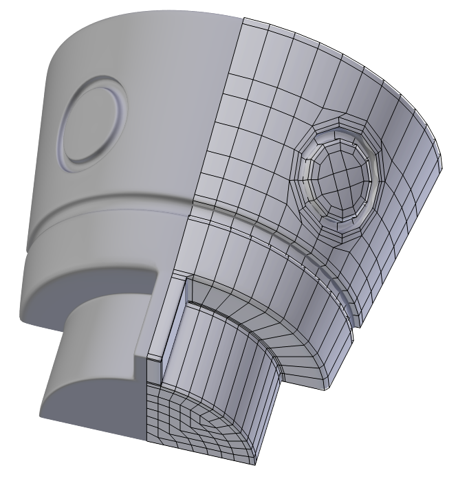
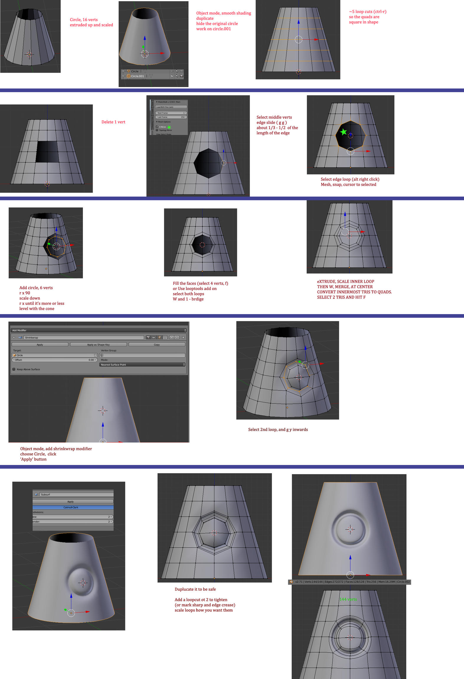
Yes, the Shrinkwrap Modifier was the ticket. Then extruded inward.
Also constructing the circle perpendicular to the cone slope to begin with helped minimize distortion of the circular shape.
When I applied the Shrinkwrap I did it on a higher poly version of my object. This helped the verts stick to more accurate coordinates across the surface.
Then I made loop cuts across the shaft that would align as closely as possible to the vertices of the inset circle.
I had the luxury of placing loop cuts wherever I needed them because the geometry was pretty simple.
Used Grid Fill on the inside of the circle (before shrinkwrapping).
By keeping the circle about the same mesh density as the shaft it actually fit in well and I was able to keep the entire mesh quads-only.
I’m pretty excited about this since these sorts of insets had caused me many headaches in the past.
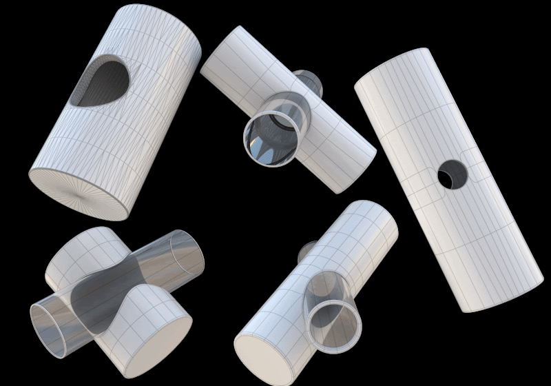
Just posting my findings for whomever may stumble upon this and find it useful. It’s not especially easy, but it can be done.
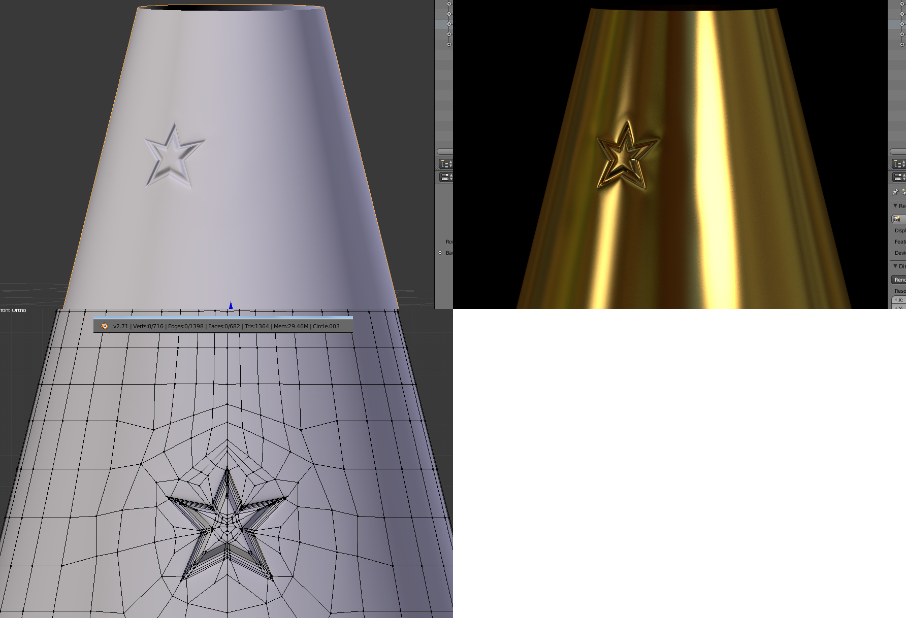
Yes, thanks for the additional example. Shows that even on a low-poly surface and inset can be made to look pretty good as long as it doesn’t disrupt the edge flow. If the pattern being inset were something like a five-pointed star (odd number symmetry) we would need to first build a border topology of an even number that could connect with the quads once shrink-wrapped. As long as care is first put into addressing that issue, any shape should theoretically work.