Growing skin - transitioning/animating between textures

I’m in the planning stages for a new project and need some help. I am trying to think about how to transition/animate between two materials on one object. What I am looking to specifically accomplish is the growing of skin on an android. I was initially thinking that I would setup the two textures on the model and use an animated alpha mask to to reveal the skin texture. One problem I thought of would be just applying one animated alpha across the model would reveal the skin but stop at the edges of the UVs and look strange. I’ve seen other tutorials on paper burning etc but not on a more complex model such as an android.

Any thoughts on how I should setup this skin growing texture animation? Thanks.

There is a bit difference in BI and Cycles. but basically, you need 2 material inputs (Node based) where output is the one you want to assign to your model.
Both materials should be interchangable via Mix node and RGB (for black or white color, animatable) as factor, which changes the color form 1 to 2.
Check out this screen shot for basic idea.


RGB node would probably just be an animated alpha that controls the factor then I would think. I don’t want a straight fade but would rather have patches of skin grow.

An example of what I am trying to achieve would be something like this from Quantic Dream.

if you want even more control, you can use a gradient texture where black would be the first part to change, and white the last, and use a setup like this:


you can insert keyframes in greater_than node to setup the speed you want.

this way you can make even more complex transitions, and i think you won’t have problems with uv’s and such.

I am actually wondering if dynamic paint would be a better tool to use to paint on and grow the skin texture areas? The gradient keyframing is more like a fade between the two textures, which doesn’t work for what I’m looking to accomplish. i want it to come on as patches and expand around the body such as in that video posted above.

The video posted above doesn’t appear to be working - I get a 404 error.

@moony the path of video is www.youtube.com/watch?v=G0KTUysrwgQ (somehow it got the BA address in the beginning)

@PixelBot I’ve created a small blend file, just to show the idea. My texture is not very complex but it can be greatly improved. if the texture has gradients inside each patch you can control from where to start growing skin. The only consideration is to keep the maximum value of each patch below the minimum value of the next patch to animate.

http://www.pasteall.org/blend/29587

Thanks for pointing out the video link. Not sure how the BA address came before it. Looks like a simple setup you have on that blend file. I see it coming in in patches by attaching the noise and divide and then the skinpatch texture. I guess you have it broke down into sections that go from black to white where black is showing through first and white it showing through last. Interesting thoughts on the black to white patches broken down on the android surface. Its similar to what I was thinking.

In the Quantic Dreams Making of video, they show Maya playblast footage where it looks like they are actually using a separate model overtop of the robotic parts to have the skin grow with some thickness. Take a look at it in the link below. Jump to 4:48 in the video to see how they approach the growing skin. Let me know your thoughts on their approach. I think they are treating it similarly to what we are doing but possibly on a separate “finished” android model and then just blending from transparency to skin texture. In blender, I wonder if a solidify modifier on the separate finished android model would add skin thickness. I may be wrong on how they are approaching it but let me know your thoughts.

well… if what you are trying to recreate is exactly what is shown in the video, then, i don’t see the need of a solidify modifier (neither a point on using it). It seems that you can do this just with the shader.

For what i see in the last video, it looks like it begins with a transparent,
then the wirelines appear as an emission.
After, there’s some color and texture in the space between this wires,
and in the end everything becomes the same shader, the skin.

One possible way is to have 3 animated masks, one for the color change in the skin, one for the transition between the transparent shader and the skin shader, and a mask for the emission shader on the top.

using the idea that i’ve posted in blend file, we will need 3 texture maps. one for the transparency, one for the wires and one for the random colors of the growing patches…

just for testing, i going to use a noise as the map for transparency and a brick texture node for the wires and random (because the brick node can do both, with fact for the wire and color for random :)), but you can use more specific textures.

I need to transform the initial gradient into the masks, based on variable that we can change.
so here the math formula for translating and scaling a linear gradient that i’ve use in the .blend file:

and because the emission shader just appears in the transition part and then disappears, i’ll also need this:


now we can put everything together:


To animate we just add keyframes to the ‘keyframe’ node.

hope it helps

Fantastic! Very thorough. I’ll have to give it a go. Thanks!

So I rebuilt your node setup and tweaked the settings and added in a simple skin SSS shader node. Its actually a pretty damn good setup for making this happen. Playing with the noise allows for the skin to come through in different patches and the bricks come through as fibers building it out like the example video.

Kudos! Below is the node setup and the result with the keyframes about two-thirds through. I’m still trying to go through the multiple math nodes to get an understanding of how you thought to use them and what they are actually doing in that setup. I need to read up a bit more. Thanks again!


this is very cool, i remember wanting to do something similar awhile back but just couldnt get the nodes right so thanks secrop

I don’t have much time now to illustrate the math in all the nodes, but if you want i can do it in the weekend. :slight_smile:
but the math is not so complicated…

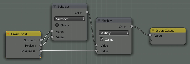
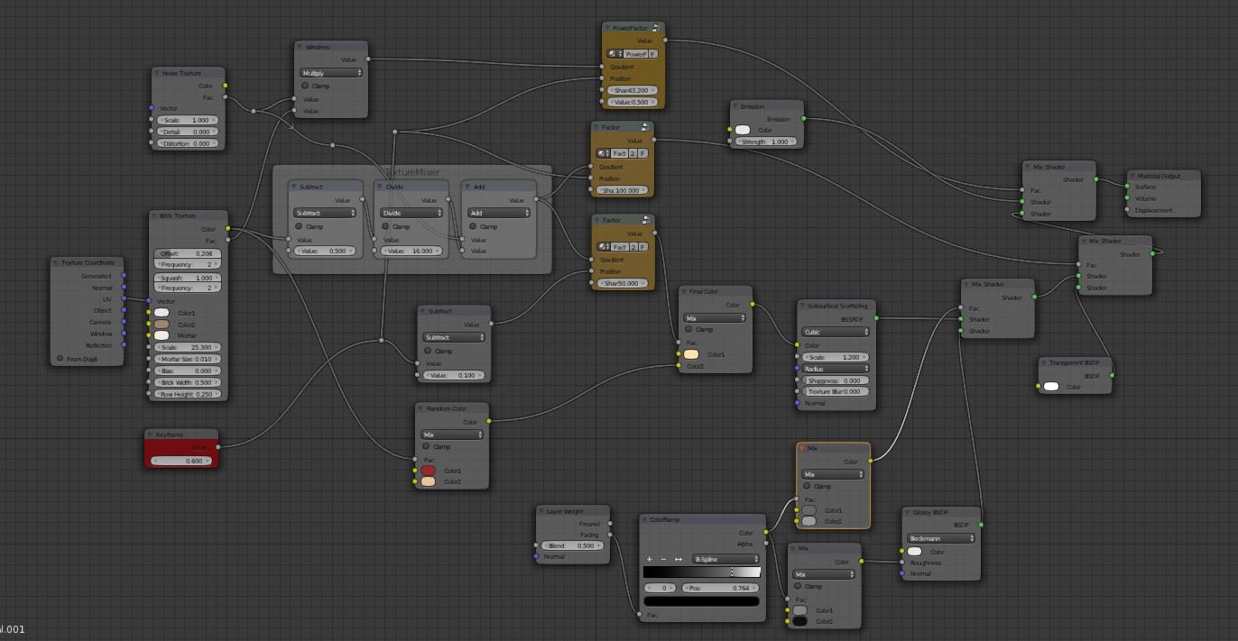
in the first node group, the subtraction makes the gradient shift from right to left… imagine the simple gradient node, where you have [0, 0.25, 0.5, 0.75, 1]. if you subtract 0.25 to the gradient, then the first point will be negative and at 1/4 position we get 0, and so on to look like [-0.25, 0, 0.25, 0.5, 0.75]. This way we can use a variable to set where 0 is going to be, just by subtracting it to the gradient.

the multiplication, that cames next, changes the slope of this gradient. if i multiply the result from the subtraction, by 2, i’ll get [-0.5, 0, 0.5, 1, 1.5]. so this way we have the [0, 1] occupying only half of the original gradient, and the rest is either bellow 0 or bigger than 1, but as we clamp the multiply node, they stay just like [ 0, 0, 0.5, 1, 1].

in the second node group i added a power of 2, which makes a parabola, changing the sign of the negative part, to positive, [0.25, 0, 0.25, 1, 2.25]. This way the gradient becomes like a fadin/fadeout, but keeping our 0 at the position we subtract initially (0.25)

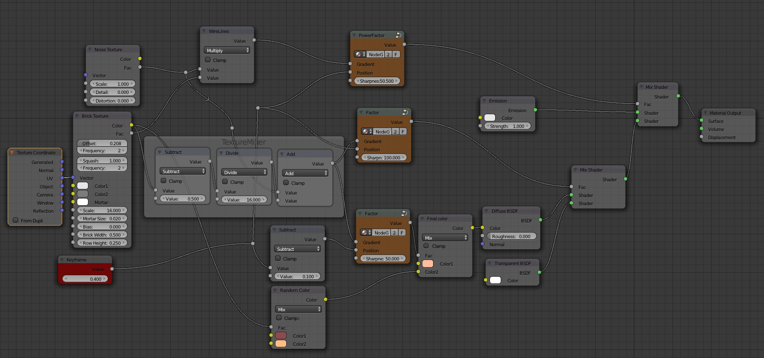
the math in the texture mixer, works more or less in the same way as a RGBmixer. So i change the brick texture limits from [0,1] to [- .5,0.5] and divided it by 16 just to keep small values, as i don’t want to have too much brick information in my mask. Here i kept the negative values, so when adding them to the noise texture, i could get both addition and subtraction. This makes the noise just a bit patchy!

the subtract node bellow the texture mixer is just for moving the mask of the color a bit to the left, and making it to stay a bit longer in the shader.

and the multiply node on the top, mixes the wire with the noise, giving the values of the noise to the white parts of the wire, and keeping everything else black… if we multiply 1 with anything we get anything, if 0 we get 0.