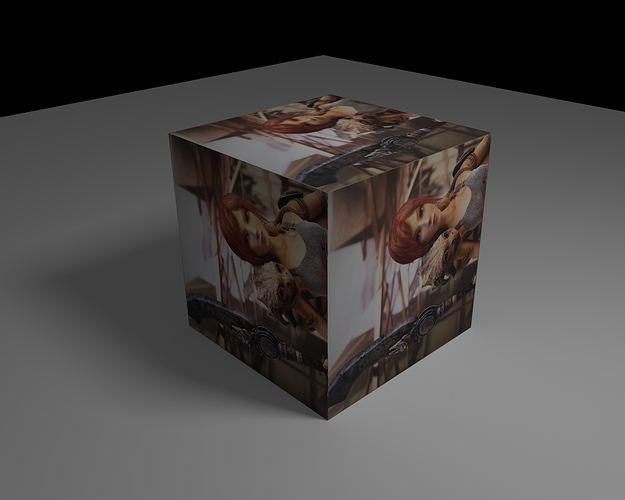
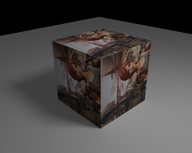
Does anyone know the math behind the UV Pass in the Blender Compositor?

I’m curious, because there’s very little information on the web about it. I understand that you can wrap material textures onto a rendered image using the “UV Pass”, but how does pass know what to calculate? How exactly does it warp the image using the four-color gradient.

Any clarification from maths peeps would be appreciated :slight_smile:

Does this help? http://cgcookie.com/blender/2012/12/10/compositing-cycles-render-passes-blender/

Otherwise try Bartek direct, he knows lots!

Sweet, thanks dude. I love that tutorial. Yeah, I just contacted Bartek and he gave me a very detailed email outlining the process. Sweet!

Well can you share what you’ve learned?

Hey all:

This is what I answered in the e-mail:

The concept of UV Pass is pretty easy:
UV Pass stores the information about COORDINATES of input image.
UV as such (not UV Pass) is the way of distorting 2d image on 3d geometry, right? You take flat image and wrap it around 3d objects. When you do it in UV image editor - you simply say which pixels of your image should be displayed on which part of the object.

UV Pass is used to re-create this process in compositing. We are no longer working on 3d geometry, but we have only 2d images. Our render is 2d and UV pass is 2d as well.
To get coordinates of 2d image we need 2 values: X and Y.
Those values are stored in UV Pass. This pass, as any other image has 4 channels: R, G, B and A. We don’t need all of them. We need only two. Information about X coordinates is stored in Red channel and Y in Green channel. You’ll notice that Blue and Alpha of UV-Pass are 1.0 all over the image. Those channels are simply ignored by the calculations.

What do the values of R and G in UV-Pass mean?

Bottom Left corner of the image is considered to have co-ordinates of X:0.0 and Y:0.0.
Top Right corner of the image is considered to have co-ordinates of X:1.0 and Y:1.0.

So say your input image has resolution of 1000 pixels by 500 pixels.
Let’s analyze one single pixel of your UV-Pass. Let’s say that its values are as follows:
R: 0.600
G: 0.200
B: 1.000
A: 1.000

B and A are ignored. Only R any G will be taken into account.
Let’s give each of the pixels of our input image an array of two numbers: X coordinate and Y coordinate. Bottom left corner of it will have coordinates of (0, 0) Top right corner: (999, 499), because our image has resolution of 1000x500 pixels. We start at zero, so we have to end at 999 on X, not 1000 and 499 on Y, not 500. Otherwise we’d get resolution of 1001x501, because pixel (0,0) counts as well.

When we plug our image to “Image” input of “Map UV” node and our UV-Pass into “UV” input of it this is what will happen:
One of the pixels of UV-Pass has values as described above (0.600, 0.200, 1.000, 1.000)
Those values tells which pixel of out image should be displayed on this pixel.
So we take 0.600 * 999 = 599.4 and we have X coordinate.
Then we do: 0.200 * 499 = 99.8 and we have Y coordinate.

Those values will probably be rounded, but I’m not sure. Maybe they get interpolated in some smart manner. Anyway. For simplicity sake let’s round them.
We get coordinates of: X: 599 and Y: 100.
This means that on the pixel that we are now analyzing the pixel with co-ordinates of 599, 100 of our input image will be displayed.

Note that values of UV-Pass are relative. When you plug some image that has different resolution than the image you used for unwrapping - you may get results you don’t expect. The resolution as such is maybe not that much important, but the aspect ratio should be maintained.

The other thing we need to take into account is that the way UV-Map node works is not perfect. When distortion is big (surfaces not facing camera) - weird results may occur. I’m not sure if this is blender specific or if it can be fixed without introducing some heavy computation that can substantially increase rendering time.

1 Like

I think there were interpolation problems with uv causing bad aliasing, especially at places of extreme distortion. I believe that maybe Sergey fixed the algorithm recently.

I checked it and it seems that the problem remained.
I don’t know if this is the issue, but I guess that instead of interpolating colors of input image, the coordinates (UV PASS itself) gets interpolated.

Here are the results. Take a closer look at them. You’ll notice issues:


Yes I see. Shame we cant just over sample the uv pass. I guess we could duplicate the scene but with over sized render values then only have a uv pass turned on.

I checked it and it seems that the problem remained.
I don’t know if this is the issue, but I guess that instead of interpolating colors of input image, the coordinates (UV PASS itself) gets interpolated.

Yes - thanks for posting your info from the email correspondence. It is a shame there is that aliasing issue in the above image. I think because a UV Pass takes very little time to render (no raytracing required), rendering an oversized version and then formatting down is probably the best method.

Thanks Bartek for explaining it.

I tried normal and oversized UV maps and while oversized UV map gives sharper result, there is still a problem with antialiasing when scaling down and it doesn’t remove problem areas from the edges. I didn’t compare to rendered version because others already shared their results and I didn’t expect this to be any different.

Normal UV pass:


Oversized UV pass:


I prepared a .blend file if someone wants to play with this. The file has

  • .exr containing relevant diffuse passes and an UV pass, rendered with Cycles
  • .exr containing an 300% size UV pass, rendered with Blender render
  • picture of Sintel

http://ubuntuone.com/2klM7J5PYSjK1WuCwqBV2G

Personally, when I think of “UV (anything) …” I find it simpler to grok this concept: that there are, in fact, t-w-o sets of coordinates associated with anything: “(X,Y,Z)” and “(U,V,W)” (where “W” is implied).

(X,Y,Z) always refers to the locations in 3-D space, “of” the face. (U,V [,W]) refers to locations “on” the face.

In both cases, we’re talking about a 3-gon of floating-point numbers … but … there are two of them.

So, in your description above, I wouldn’t refer to (X,Y) coordinates. Instead, I would refer to (U,V) coordinates. I think that this nomenclature makes the essential idea much clearer. By consistently using different sets of letters, we remove at least some of the inherent ambiguity in our conversations.

Obviously, we’re using “image files” in all of these cases … a very-familiar standard format which happens to use “yet another 3-gon nomenclature” to refer to its “triplets of floating-point numbers.” That nomenclature is: (R,G,B).

But, when the dust finally settles, to the digital computer it’s really all the same: “floating-point numbers in groups of three. Pick a letter. Any letter…” The only ones who stand to get totally-confused are the humans. :slight_smile:

Thanks Bartek. I used your math for buidling php script. But something is wrong. Look on my sample: http://community.thefoundry.co.uk/discussion/content.aspx?id=25679&t=10

Grid is circulated - distorted on high U and high V values. Maybe it`s fault of PHP rounding (5 digits after comma).

Maybe there should be some more variables in that math. After multiplying of color values by position my outputs looks like on link above.

Any tips?

I have a question. Can I make the blue channel not be 1? I see that the UV channels of redshift all have red, green and blue information in them. Blender does not have blue information in it. I don’t know if it is correct. How do I go about it?