I found where the looptools are but it’s over my head how to use it on the model.
On the top of it, this time there are faces that are n-gons with more than four vertices on that spiral-like area,
and the x and y positions shouldn’t be modified by a relaxing function.
Lazur! Hi buddy! Kinda cool that we can maintain usernames from forum to forum, eh?
Anyway, DLed your file. Don’t see the problem! You must be aware that you have many nonplanar quads in there; as well more Ngons than I am comfy with, still you must know what you are doing with those.
Is there a rendering problem? In the same general area you have three or four non manifold edges. From the select menu you can find and resolve them.
I can’t see any other obvious probs. If the display is all you are worrying about, when you say you would like to clean up the model I don’t think you can. dissolving the edges that are showing just mkes another edge light up. I’m sure you know how to show all the edges (properties, object, display)…
I’m thinking of starting a work in progress thread here as things are getting closer together,
that may make a better explanation for itself.
I wanted to preserve a good cilinder surface,
thus the intersection parts were knife projected all the way, creating those ngons.
Somehow the smooth shading isn’t right though,
but with that high facecount it’s not that big problem I hope even if the shading is flat.
The problem appears when the object is selected in wireframe, object mode.
It appears that there are straight “edges” in a “smooth surface”.
I assume something is not right from that -even if the faces are redrawn from vertices,
with the same coordinates.
Simply recalculating the normals doesn’t help more than as it is now.
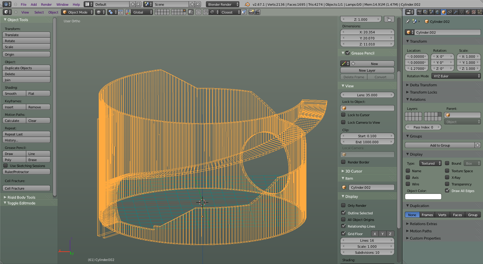
I thought that’s what you meant, Lazur, but I think you are barking up a telephone pole here. In object mode, you can choose the option to not display all the wireframe in order to keep the screen from just becoming unreadable. You can choose or not, in the object properties under display. See the screenshot I attached in my earlier post. This is what your model looks like with the ‘show all edges’ option checked. You will notice it is in object mode! You may not have seen that…
The edges that Blender chooses to display in the thinned out view - well, I suspect she is using face angle to decide which ones get drawn and every so often an edge is deemed ‘displayable’ that maybe you thought was just like the others… I did notice the faces near the top were quite nonplanar, that might be another criterion.
What I am saying is that you should check the box ‘show all edges’ to really see the model and not base any decisions on the way it looks without that box checked…
Good luck!
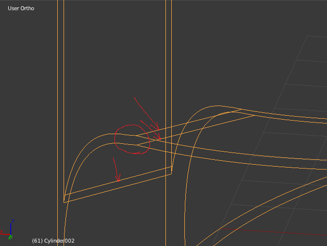
The surface should be continous, as a cilinder, thus, with an edge being displayed along the way, it shows something is off.
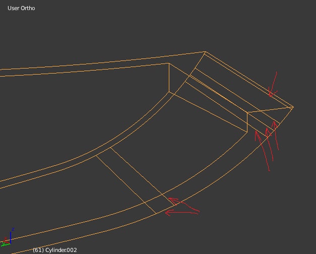
Notice that on the second screenshot, the upper part doesn’t have any “wrong” edges,
but the one below, with very similar geometry, has.
Actually there is no non-planair face modelled intentionally.
The surface will be a ceiling, so it is the lower part which the model is based upon.
The inner and outer vertical surfaces are cilinders with vertical axises,
the starting of the curved part is a cilinder with a horizontal axis,
which is then followed by a spiral surface with a fixed angle.
At the top, that angle increases so that the horizontal edges of the surface follow
the cutline of the inner cilinder surface and a smaller cilinder with a horizontal axis
-which cilinder has the same radius as the one wich with the surface started on the other end.
I know it’s not 100% geometrically correct,
where the cilinder turns to a spiral surface it is theoretically off.
But why not the possibility to create a smooth surface from that?
That upper part shouldn’t have any problems, as all the edges are horizontal.
By the construction -the cutline was duplicated, and scaled only in x and y directions equally.
In the linked thread I was facing the exact same problem.
How a seemingly smooth surface can be handled as one continuous smooth surface,
without any breaks at any edges.
The looptool’s relax was mentioned, but I have no idea how it should work on this.
(Well tried the bridge option for other parts, which I ran into some issues, but I could solve those.)
Strangely now with the draw all edges option unset all the edges are displayed in wireframe, object mode, on any new cilinder added.
Is there a setting that I missed?