I’m posting this to perhaps find out if there are alternative solutions to this problem that has been bugging me for a while.
It’s possible that I’ve completely messed up the topology for this kind of shape but I did try several approaches to keep the subsurf from distorting it.
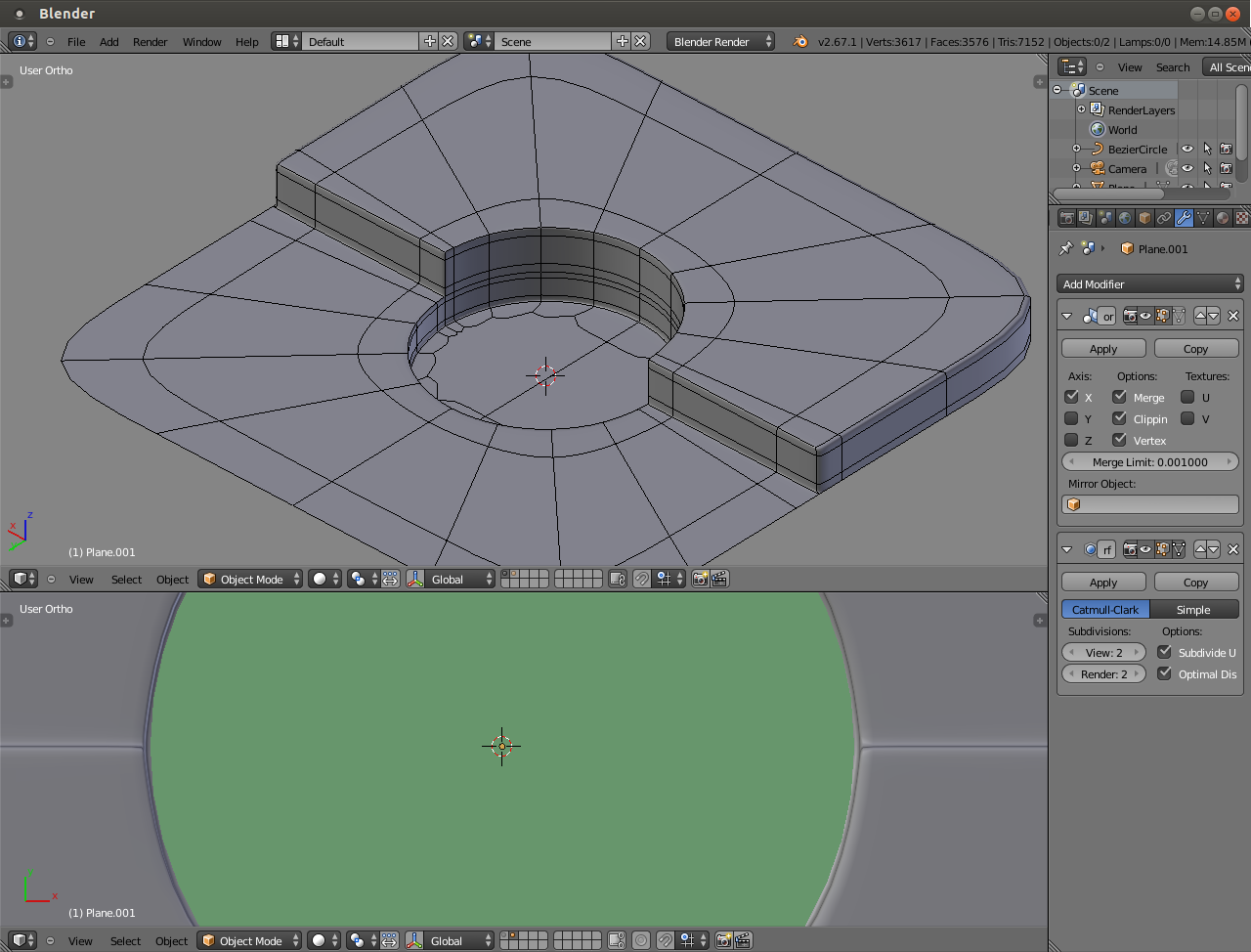
The problem is to keep symmetric circular shape with subsurf when the shape is a cutout and not a continuous circle.
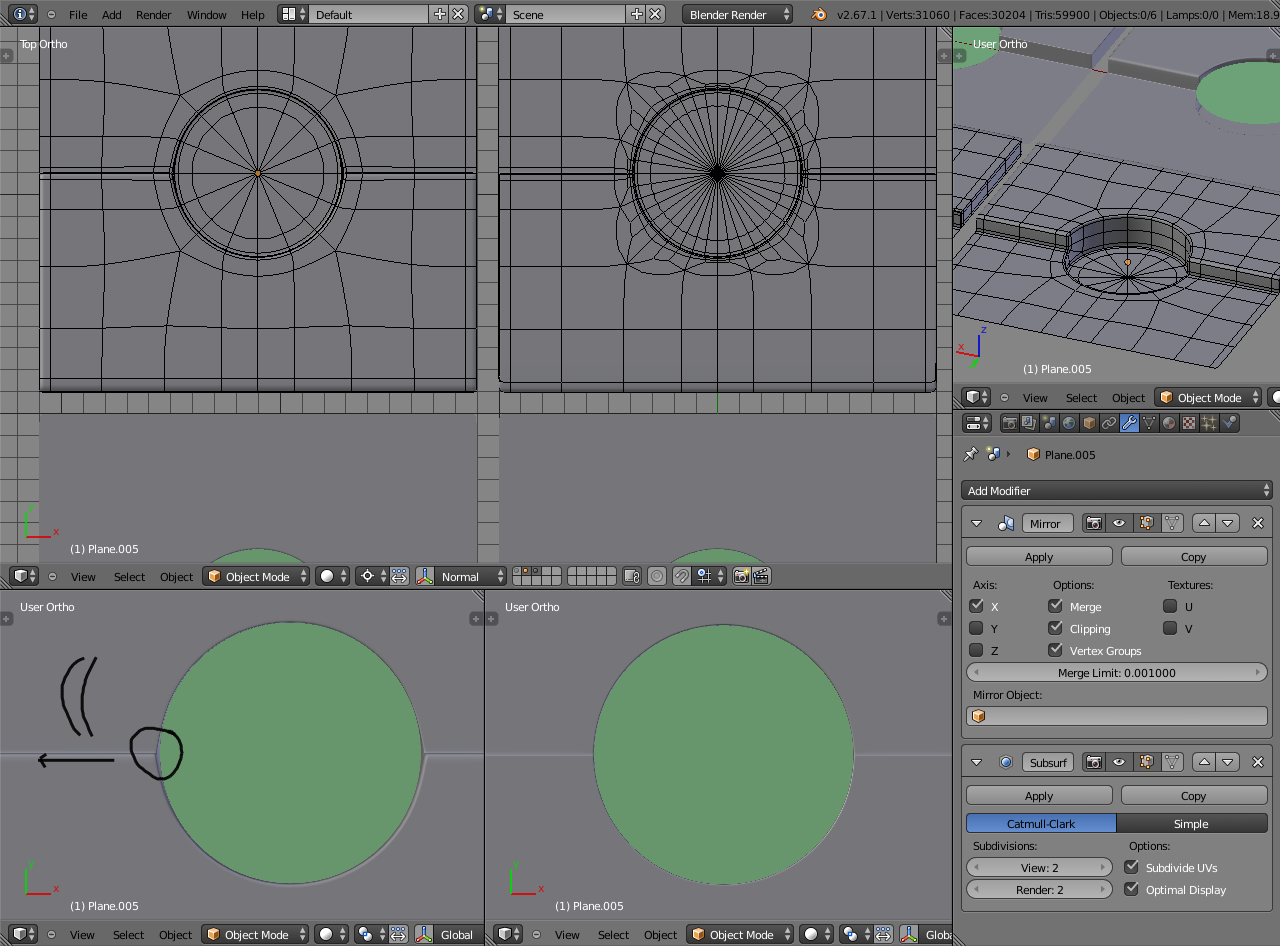
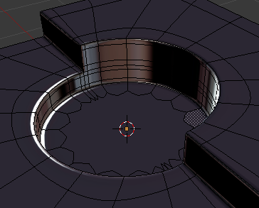
Green object in the picture is a high resolution bezier circle to give a reference of a perfect circle. In the bottom left corner it’s (hopefully) visible that subsurf rounds the edge & corner and pulls them away so that the shape is no longer symmetrical. In the top left and right corners are wireframes for that.
One solution of course is to add more geometry to confine the distortion to a much smaller area and then move the edges a bit closer to the center. (Shown in the picture in the middle top and bottom). This works quite well, because you have to zoom very close before the distortion is visible.
Another obvious solution is not to use subdivision surface modifier at all but that’s not how puzzles are made.
rounding_problem.blend (573 KB)
(I included a basic shape and a reference circle on the first layer if someone wants to have a try)
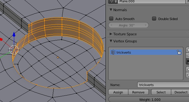
And because cheating is a part of the modelling process to make life easier instead of trying to add even more support edge to fight against the subsurf pulling the side of the circle, i would make those vertices into a vertex group
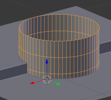
Then i would make a cylinder (from the base of that hole duplicated and made a separate object),
Add a subsurf of the same exact level as used in the model, and apply it
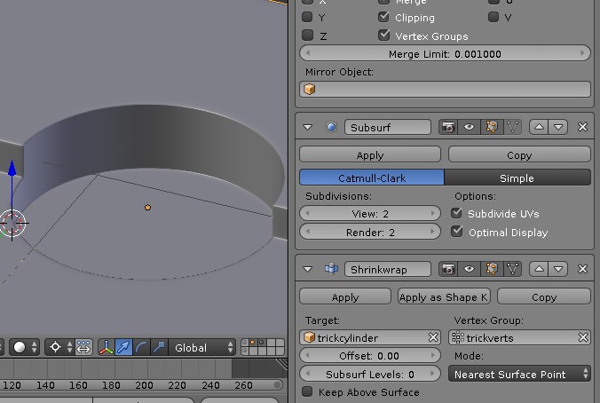
And on the model, add a Shrinkwrap modifier targetting that cylinder and only influencing the vertice from the vertex group
Then hiding from the view that cylinder should complete the trick to avoid the subsurf getting in my way in the side of the circular opening
If you want to keep 16-sided circle, you get a better form if you rotate base circle 11.25 degrees. So that, segmented free standing circular edge is not “sitting on” 16 vertices that define the circle. This will require you to divide two opposing edges to form that step. But end result is you will have hard 90 degrees angular base geometry where subdivision must take place:
subsurf is meant mostly for orgniac object not mechanical things like you have here
not saying it cannot be done here
another trick here would be to make 2 objects one for the top and one for the bottom
and if nor for animation there is nothing saying you cannot use Ngon on the bottom part either!
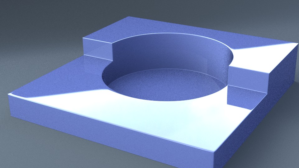
The point wasn’t how to get that kind of object done but find different ways to fight subsurf from distorting the circular shape.
Many hard surface objects have that kind of cutout, or similar. Alloy wheels in cars for example have all sorts of cuts for bolt holes.
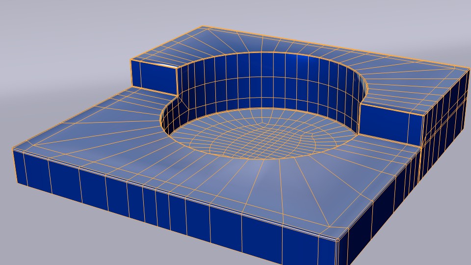
Of course it would be better to get it done with as few vertices on the circle as possible because it’s modifier’s job to add the rest, and to have some room to decide how many vertices are needed there and keep the subsurf level moderate for the whole object.
Otherwise it doesn’t matter, I just did those objects quickly by subdividing the plane and decided to have 16 vertices on the base circle, but not in any particular reason.
@Sanctuary
It would’ve been enough for me if you just said “Use shrinkwrap with a vertex group to keep the vertices in place” No matter, that is another good addition to your mini-tutorial collection.
That certainly works and is quick to do for some closeup shot that reveals the cutout shape. Thank you.
@ridix
Not sure if this is what you meant. At first I thought that doesn’t do anything to get rid of the problem but making it like that does help to quickly get rid of the hard edge that forms there and compensate for the distortion by moving the vertices towards the center. Very nice, thank you.
You need a circle spline as a guide, then manually adjust the mesh so that it follows the curvature of the circle spline you’re using for reference. This is how I’ve been taught to do it when it comes to having add additional edges in to a circular object, it destroys the circle shape at the beginning but whack a circle spline over it and adjust to suit.


 No matter, that is another good addition to your mini-tutorial collection.